BMS Board Power Supply: How to Power, Charge and Service Battery Management Systems
Published: September 2026
Reading time: 9 min
Audience: battery pack manufacturers, energy storage and light e-mobility OEMs, production engineers, and sourcing teams specifying the external supplies used to charge, wake, test and service BMS-equipped packs
By Han — Paiyi Power, a power adapter and external power supply manufacturer. We do not build BMS boards — we build the external supplies that charge, wake, test and service the packs that contain them, from 200 pcs per model.
Last updated: 8 September 2026.
Contents
Direct answer: what power supply does a BMS board need?
Almost none, and that is the trap. A battery management board typically draws its operating power from the pack it protects — tens of microamps in sleep, a few milliamps when active, plus whatever the balancing resistors dissipate. So there is usually no “BMS power supply” in the sense of a dedicated adapter feeding the board.
The external power supply matters in three places, and confusing them is what causes most field problems:
- Charging: the charger or power supply that pushes energy into the pack through the BMS. This is sized by capacity and charge window, and it must respect the BMS’s protection behaviour.
- Waking: the supply that recovers a pack whose BMS has disconnected it. Once the BMS opens its discharge and charge MOSFETs, the pack terminals can read zero volts, and a charger that looks for a battery before it starts will simply refuse to charge.
- Production and service: the stable, current-limited bench supply used to flash firmware, calibrate, balance and run end-of-line tests — and the workshop supply used to bring stored packs back to a healthy state of charge.
The single most useful specification decision: require your charger to deliver output even when it detects no battery, or add a wake-up preconditioning step to your service procedure. Most “dead” packs returned under warranty are not dead.
Pack classes and what the external supply has to do
| Application | Typical pack | External supply role | Key requirement |
|---|---|---|---|
| Home / commercial ESS | 48V LiFePO4, 5–30kWh | Bulk charging, top balancing, storage maintenance | Long unattended operation, low standby draw |
| E-bike / e-scooter | 36V / 48V, 10–25Ah | Daily charge, deep-discharge recovery | Zero-volt wake capability, connector durability |
| Portable power station | 12–48V internal, 300W–3kWh | AC adapter, solar input, car input | Wide input range, multi-source arbitration |
| Light EV / golf / utility | 48–72V | Onboard or offboard charging | Pre-charge handling, CAN communication |
| Industrial backup / UPS | 24V or 48V, long float life | Float charging and periodic test | Stable float voltage, temperature compensation |
| Production line | Any of the above | Flash, calibrate, balance, EOL test | Low noise, accurate current limit, fast transient recovery |

The zero-volt problem: why “dead” packs usually are not
When a BMS trips on under-voltage, it opens its discharge MOSFET and, on many designs, the charge MOSFET too. The protection is doing its job: the cells are already low, and further discharge would damage them. But from the outside the pack now looks like an open circuit. Terminal voltage reads near zero.
A conventional charger sees no battery, concludes nothing is connected, and stays off. The pack sits in a warehouse or on a customer’s shelf for three months, self-discharging further, until the cells fall below the point where they can be safely recovered. The pack is then genuinely dead — killed by the protection that was meant to save it.
Three fixes, in order of preference
- Specify zero-volt (0V) charge capability in the charger. The supply outputs a limited current regardless of whether it senses a battery, which lets the BMS wake and re-close its charge path. This is the cleanest fix and belongs in your charger specification from the start.
- Design a wake-up input on the BMS that powers the board from the charger side of the protection MOSFETs, before the pack path is enabled.
- Document a service procedure using a bench supply with a hard current limit to bring the pack up manually. This works, but it depends on a technician doing it correctly, every time.
If you are buying chargers for a pack program, make “0V / wake-up charge” a line item in the RFQ. It costs almost nothing to include at design time and it converts a class of warranty returns into a non-event.
Isolation and communication: where the supply design gets real
The BMS talks to the outside world over CAN, RS485, SMBus or UART. Those interfaces are the reason external supplies for BMS work need more thought than their wattage suggests.
- Isolated transceivers need isolated power. If the BMS communication port is isolated, the supply feeding the transceiver must carry that isolation too. Ask your BMS vendor which isolation grade the port requires — basic or reinforced — and match the supply to it. Do not guess; the insulation system is a safety function.
- Ground loops corrupt measurements. If the external supply ties the pack negative to earth and another piece of test equipment does the same at a different point, current flows through the sense wiring and cell-voltage readings drift. This shows up as packs failing end-of-line calibration for no apparent reason.
- Creepage and clearance are set by the working voltage, not the nominal voltage. A “48V” pack is not 48V at full charge, and transients push it higher. Specify to the maximum working voltage with margin, and remember that 60V DC is the SELV boundary under IEC 62368-1.
- Surge and load dump. Packs connected to motors, contactors and long harnesses see inductive kickback and switching surges. A supply with only basic input protection will fail in the field in ways that look like random infant mortality.
Production-line supplies: flashing, balancing and end-of-line test
On the line, the external supply is a measurement instrument as much as a power source. If its output noise or its current-limit behaviour is unstable, your end-of-line data is noise, and you will scrap good packs and ship marginal ones.
| Station | What the supply does | Specification that matters |
|---|---|---|
| Firmware flash | Boots the BMS before the pack is live | Clean output, no dropouts, fast enable |
| Cell calibration | Powers the board while reference voltages are applied | Low ripple, stable over temperature, isolated where needed |
| Top balancing | Holds the pack at a set point for hours | Continuous rating at ambient, not peak rating |
| EOL functional test | Drives load steps to verify protection thresholds | Fast transient recovery, accurate current limit |
| Storage / shipping charge | Brings packs to 30–50% state of charge | Repeatability, unattended safety behaviour |
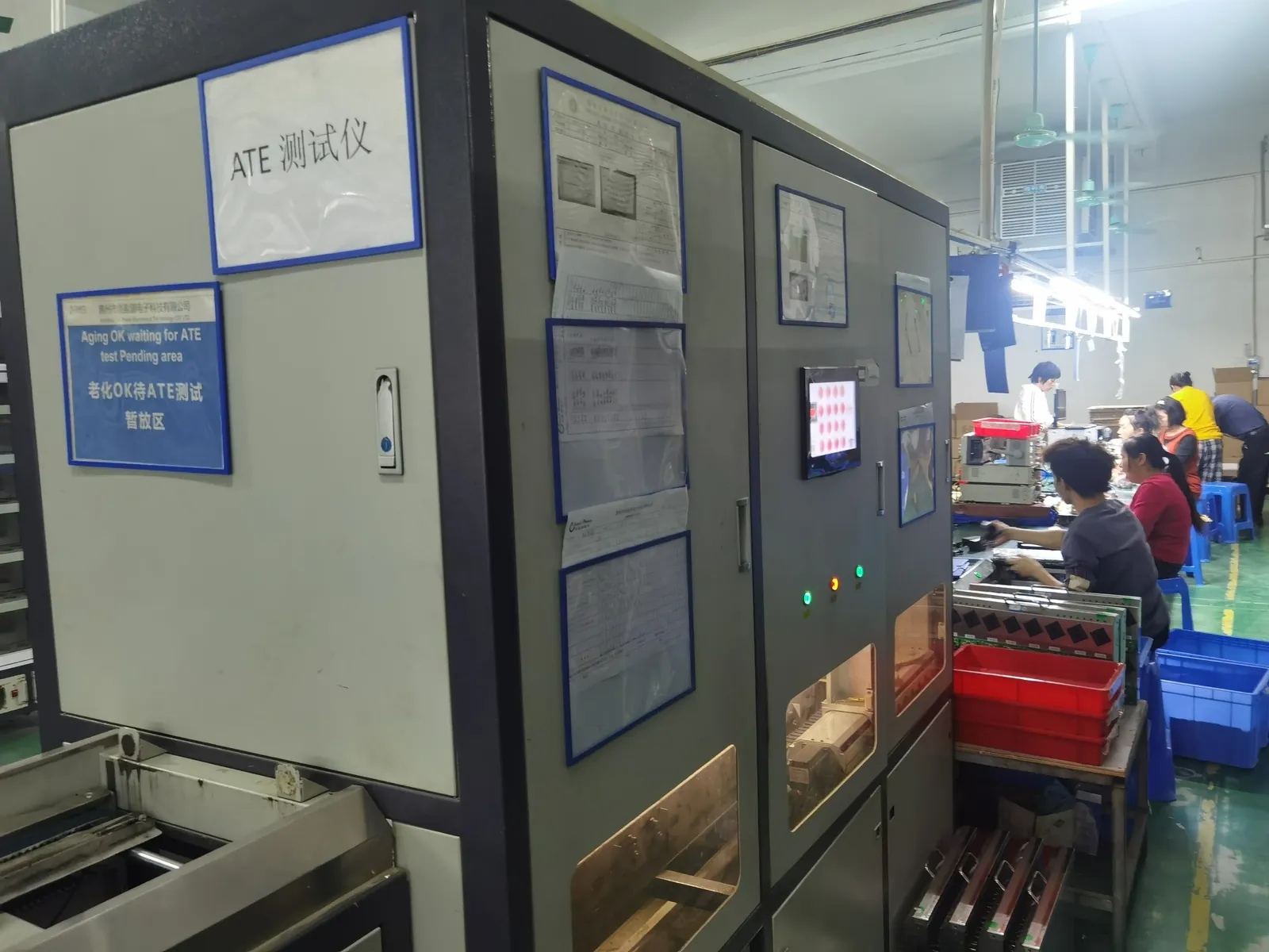
Our units for this kind of duty are verified on ATE under load, then burned in before packing, because a supply that drifts on the line quietly corrupts every measurement taken downstream of it.
Specification checklist for a BMS-related external supply
- Output voltage and its tolerance across line, load and temperature — not just at the nominal point.
- Current limit behaviour: constant-current fold-back, hiccup, or latch. For charging, constant current with a clean transition is usually right.
- Zero-volt / wake-up capability if the pack can ever arrive with the BMS open.
- Isolation grade matched to the communication port: basic or reinforced, with the test voltage stated.
- Ripple and noise in mV peak-to-peak at your actual load, since it couples into cell measurement.
- Reverse-polarity and short-circuit behaviour, including whether recovery is automatic.
- Input surge and transient immunity appropriate to the installation.
- Ambient range and derating curve for the actual site, not a 25°C bench.
- Connector and cable: keyed against wrong-pack insertion, rated for the mating cycles the line or the user will impose.
- Certificates as reports for your target markets, with numbers you can verify.
Six mistakes we see repeatedly
- No 0V charge capability — the leading cause of “dead on arrival” returns.
- Charger sized to pack capacity alone, ignoring the charge window and balancing time.
- Earthed supply creating a ground loop through the sense harness, corrupting calibration.
- Isolation grade assumed rather than specified against the BMS communication port.
- Float voltage set without temperature compensation in backup applications.
- Bench supply used as production equipment, with no calibration schedule and no current-limit accuracy data.
Working with a supply manufacturer on a BMS program
We build external adapters and power supplies from 5W to 240W, including custom and modified-standard designs for battery programs. To be precise about scope: we do not manufacture BMS boards and we do not certify battery packs. What we supply is the charging, wake-up, service and end-of-line test power that those programs need.
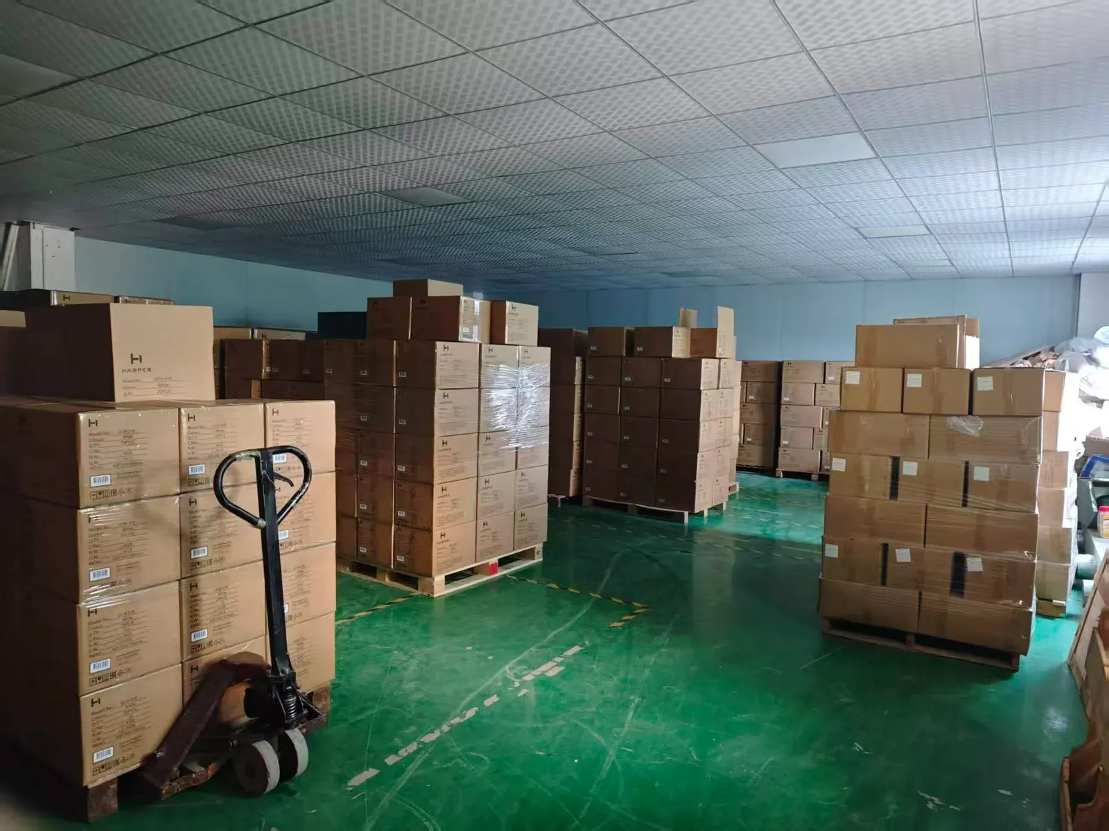
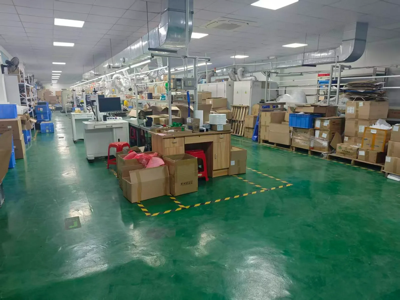
Working parameters: MOQ from 200 pcs per model, 5–6 week lead time after sample approval, 100% ATE test and inspection before shipment, capacity up to 150,000 pcs per month across four lines. Board-level SMT is subcontracted to a qualified partner with incoming inspection; final assembly, functional test, burn-in and QC are ours.
Related reading: industrial power supply applications for the wider vertical picture, power supply solutions for robotics for the motive side, and how to test a power supply for the acceptance limits we sign off to.
Frequently asked questions about BMS board power supply
Does a BMS board need its own power supply?
Usually no. The board is powered by the pack it monitors, drawing tens of microamps in sleep and milliamps when active. External supplies are needed for charging, waking a protected pack, and production or service work.
Why won’t my charger start on a flat pack?
Because the BMS has opened its protection MOSFETs and the charger sees no battery. You need a charger with zero-volt or wake-up capability, or a documented bench procedure with a hard current limit.
How do I size a charger for a battery pack?
Pack capacity in amp-hours divided by the charge hours you can accept, then add margin for losses and balancing time — and then confirm the BMS and cells accept that current. Balancing at the top of charge often takes longer than the bulk charge itself.
What isolation does the supply need for BMS communication?
Whatever your BMS communication port requires. If the CAN or RS485 transceiver is isolated, the supply feeding it must carry the same isolation grade, basic or reinforced, with the test voltage stated. Ask the BMS vendor; do not assume.
Can a noisy supply corrupt cell-voltage readings?
Yes. Ripple on the supply couples into the measurement front end, and ground loops created by earthed supplies push current through the sense wiring. Both show up as calibration failures that look inexplicable.
Do you make BMS boards?
No. We make the external power supplies used to charge, wake, test and service packs. If you need a BMS, we are not the right supplier, and we would rather say so than waste your sampling cycle.
What happens if I connect the charger backwards?
It depends on the design, so specify it. Ask whether reverse polarity protection is a diode, a MOSFET or a fuse, and whether the unit recovers automatically or needs to go back to the workshop.
Is 48V always safe to work on?
48V nominal is inside the 60V DC SELV boundary, which simplifies insulation requirements — but a fully charged 48V pack sits well above nominal, and transients push higher. Design to maximum working voltage, not nominal.
What MOQ and lead time should I expect?
From 200 pcs per model, 5–6 weeks after sample approval. Modified-standard designs usually need no tooling. Every unit is ATE-tested, burned in and inspected before packing.
Sources
- IEC 62368-1 — Safety of IT and AV equipment (SELV limits)
- IEC 62133 — Safety of secondary lithium cells and batteries
- IEC 61000-6-2 / 61000-6-4 — Generic EMC standards for industrial environments
- U.S. DOE — External Power Supply efficiency (Level VI)
- UL — Energy storage and battery safety standards overview