
Energy Storage Power & BMS Engineering
Energy Storage Power & BMS Platforms
PaiYi develops both battery management boards (BMS) and the power platforms that surround them for energy storage applications. The electrical targets below remain open until the battery stack, BMS topology, target market and operating environment are confirmed.
BMS Power Supply Design Priorities
The final architecture should be selected from real system requirements rather than a fixed catalogue assumption.
Input and Output Definition
Confirm the input source, normal operating range, transient conditions, required output rails, regulation and sequencing expectations.
Power and Standby Demand
Define continuous and peak loads together with sleep, wake-up and standby consumption targets across operating modes.
Isolation and Grounding
Review isolation boundaries, working voltage, grounding strategy, common-mode conditions and insulation coordination requirements.
Protection and Fault Behavior
Specify the required input, output and thermal protection behavior, fault reporting expectations and recovery method.
Temperature and Lifetime
Set the operating and storage temperature ranges, thermal constraints, cooling conditions and intended service-life target.
EMC and System Integration
Evaluate emissions, immunity, surge and transient requirements in the actual battery, PCS and EMS installation environment.
Preliminary Specification Worksheet
Values are intentionally left open for engineering review. They will be completed only after the project requirements are supplied.
Integration with PCS and EMS Environments
A BMS auxiliary supply operates inside a wider electrical system. Review of the surrounding equipment helps prevent late changes during validation.
System Context to Confirm
Battery-stack voltage and switching transients, PCS operating modes, grounding and isolation boundaries, nearby communication wiring, enclosure conditions, start-up and shutdown sequencing, fault states, and the target EMC test environment.
OEM Development Scope
The project scope is defined jointly and documented before sampling.
Electrical and Mechanical Options
- Input and output configuration
- Power, isolation and standby targets
- Protection and thermal design scope
- Housing, dimensions, mounting and connectors
- Cable, label and packaging requirements
Information Needed for Evaluation
- Battery chemistry, stack voltage and BMS topology
- Load profile and required output rails
- Target market and compliance requirements
- Operating environment and service-life expectation
- Mechanical drawing, connector definition and order forecast
From Requirement Review to Production
Requirement Review
Confirm the electrical, mechanical, environmental and compliance inputs.
Architecture Proposal
Define the power platform, open items, validation scope and development path.
Sample Validation
Evaluate samples against agreed operating modes, faults and system conditions.
Production Readiness
Finalize approved specifications, documentation and manufacturing requirements.
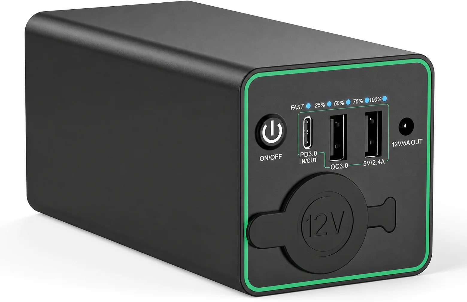
86.58Wh Portable Power Station → OEM Reference Design
A shipped example of our OEM work: this 86.58Wh portable power station was engineered and brought to mass production by us for an outdoor-power brand, and is selling really well on Amazon across the dash cam and camping categories.
- Developed as a complete unit. System design, electronics and final assembly handled in our Huizhou plant, from concept to mass production.
- Certified and fully protected. FCC, CE and RoHS certification arranged before mass production, with over-current, over-voltage, short-circuit and temperature protection built in.
- Sized for real use. 86.58Wh keeps a dash cam running through the night, recharges in about four hours over USB-C PD, and stays under the 100Wh airline limit.
- Higher power, same team. We develop, design and produce higher-output outdoor power stations for projects that need more than this 86.58Wh class.
Frequently Asked Questions
What power do you provide for energy storage systems?
Do you integrate with PCS and EMS environments?
Can you deliver BMS auxiliary power and charging together?
What standards apply to ESS power supplies?
Discuss Your Energy Storage Power & BMS Requirements
Share the available specification, block diagram or target operating conditions for an initial engineering review.