Why Power Adapters Fail: The Failure Modes Behind Field Returns and How Factories Prevent Them
Published: September 2026
Reading time: 8 min
Audience: brand owners, quality engineers and procurement teams trying to understand power adapter field returns and how to prevent them at the design and factory stage
By Han — Paiyi Power, an OEM/ODM power adapter manufacturer with 100% ATE testing and burn-in before shipment.
Last updated: 9 September 2026.
Contents
Direct answer: why do power adapters fail?
Power adapters fail in seven known, preventable ways — electrolytic capacitor aging, connector wear and abuse, surge damage, thermal cycling fatigue, moisture and corrosion, manufacturing escapes, and application overload — and each mode has a design countermeasure and a production test that catches it. When field returns spike, the cause is almost always one of two gaps: a specification that ignored a real-world stress, or a factory step that was skipped to save cost. Understanding the failure modes turns “the adapter died” from a mystery into an engineering conversation — which is exactly what this guide is for.
The seven failure modes
1. Electrolytic capacitor aging — heat is the clock
The electrolytic capacitors in the output and input stages age with temperature, and the rule of thumb is brutal: every 10°C cooler roughly doubles capacitor life. An adapter run continuously at its rating inside a warm cabinet ages several times faster than the same design loafing at half load in open air. This is why derating curves, efficiency and placement matter more than most buyers expect — see our mini PC power guide for the thermal coupling story.
2. Connector wear and cable abuse
The DC plug, the socket and the cable’s strain relief take all the mechanical abuse. Barrel connectors wear with insertion cycles, cables fatigue where they flex, and untrained users yank by the cord. Failures show up as intermittent output — the adapter “works” when wiggled — which users report as a dead device.
3. Surge and grid events
Input stages die to lightning-adjacent surges, load dumps from shared circuits and grid switching. A MOV-based input degrades with every surge it absorbs until one event finishes it. Installations with motors, HVAC and long building runs need real input immunity — the differentiator we describe in our network power guide.
4. Thermal cycling and solder fatigue
Power-on and power-off cycles flex the solder joints as parts expand and contract. Marginal solder work survives the factory and fails after a few hundred cycles — which is why the failure curve of a bad batch looks fine at first audit and ugly six months later.
5. Moisture, dust and corrosion
Coastal, food-processing and outdoor-adjacent environments attack connectors and component legs long before the electronics notice. Conformal coating on the PCB is the standard countermeasure — it is an option you must ask for, not a default.
6. Manufacturing escapes
Cold solder joints, a wrong component value, a missing insulation tape — escapes are rare in a disciplined line and certain in a sloppy one. The defences are incoming inspection, 100% ATE functional testing, burn-in and a change-control agreement, as laid out in our OEM agreement guide.
7. Application overload
The adapter was fine; the application was wrong — undersized for the load, run continuously above its derated capacity, or paired with a device that draws beyond the agreed peak. This mode is a specification failure, and it is the reason sizing discipline exists in every guide on this blog.
Design, production or application: who owns each failure
| Failure mode | Root-cause layer | Prevention | Test that catches it |
|---|---|---|---|
| Capacitor aging | Design + application heat | Higher-temp caps, derating, efficiency | Thermal run, capacitor life calculation |
| Connector wear | Design + user abuse | Connector spec, strain relief rating | Pull test, insertion-cycle test |
| Surge damage | Application environment | Input stage class, MOV + follow-up | Surge immunity test |
| Solder fatigue | Production | Process discipline, QC | Thermal cycling, burn-in |
| Moisture / corrosion | Application environment | Conformal coating option | Sample inspection after humidity exposure |
| Manufacturing escapes | Production | IQC, ATE 100%, change control | ATE functional test, burn-in |
| Application overload | Specification | Sizing discipline, defined peak budget | Load test with the real device |
How the factory catches them before shipment
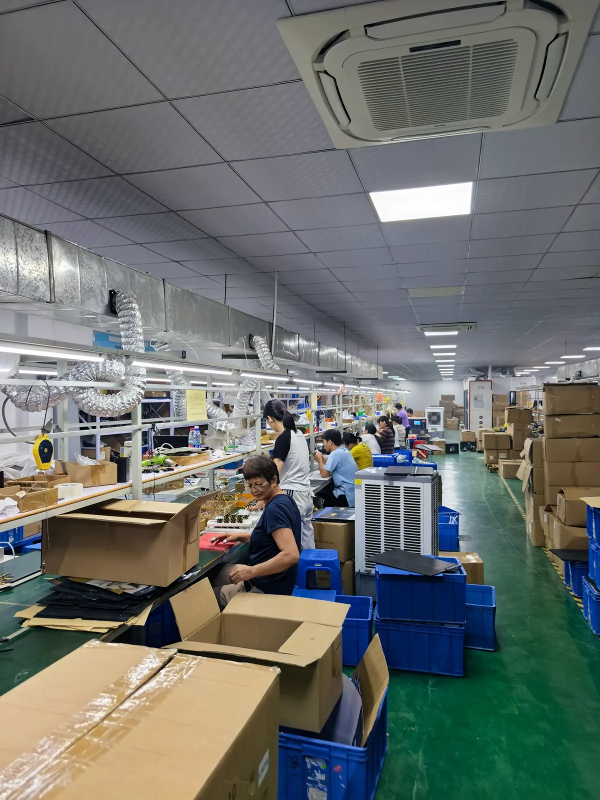
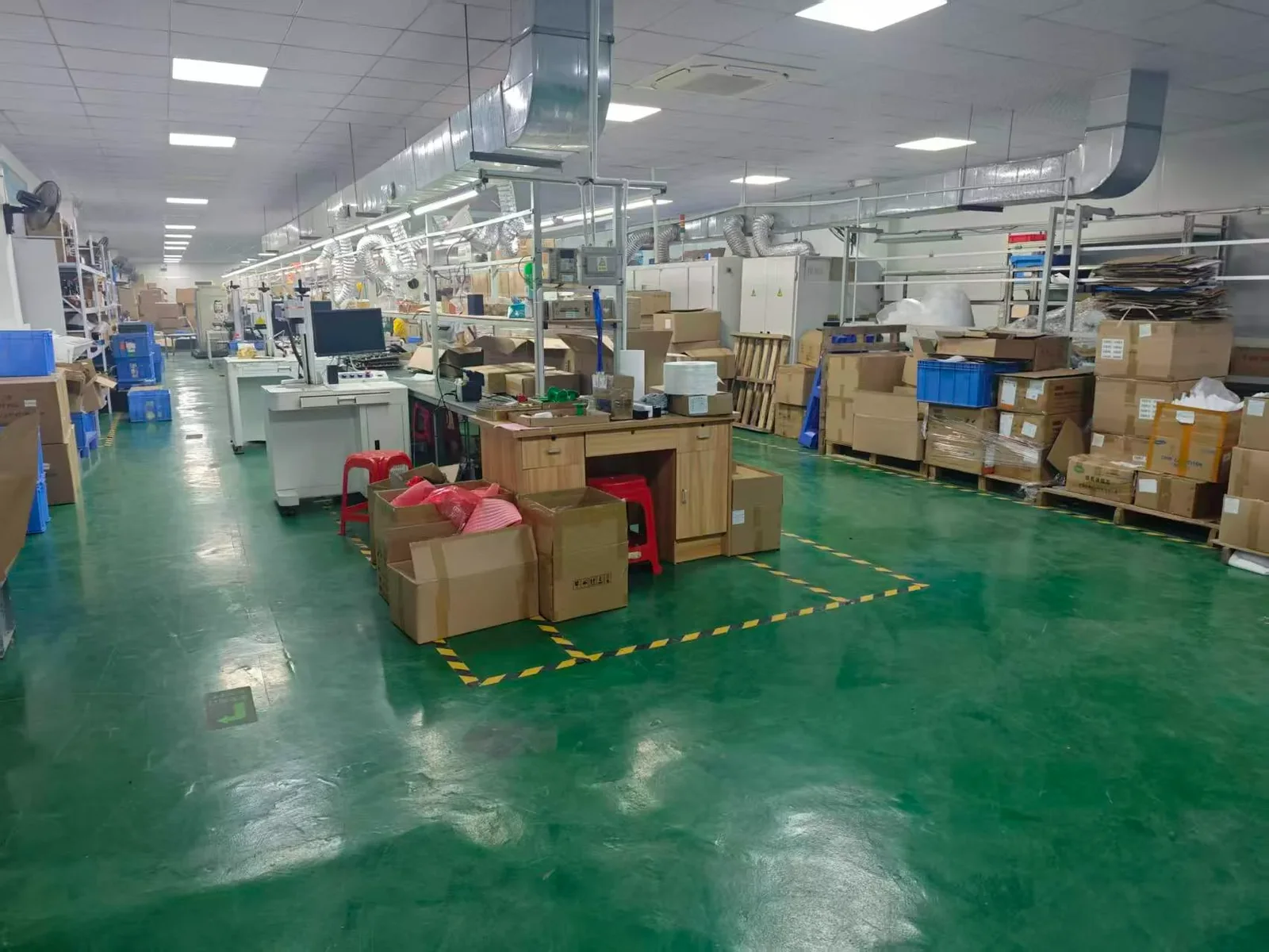
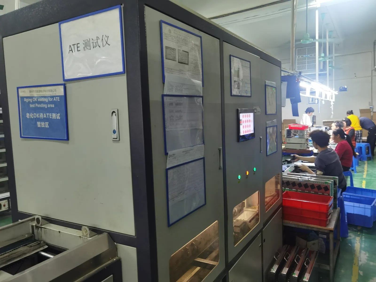
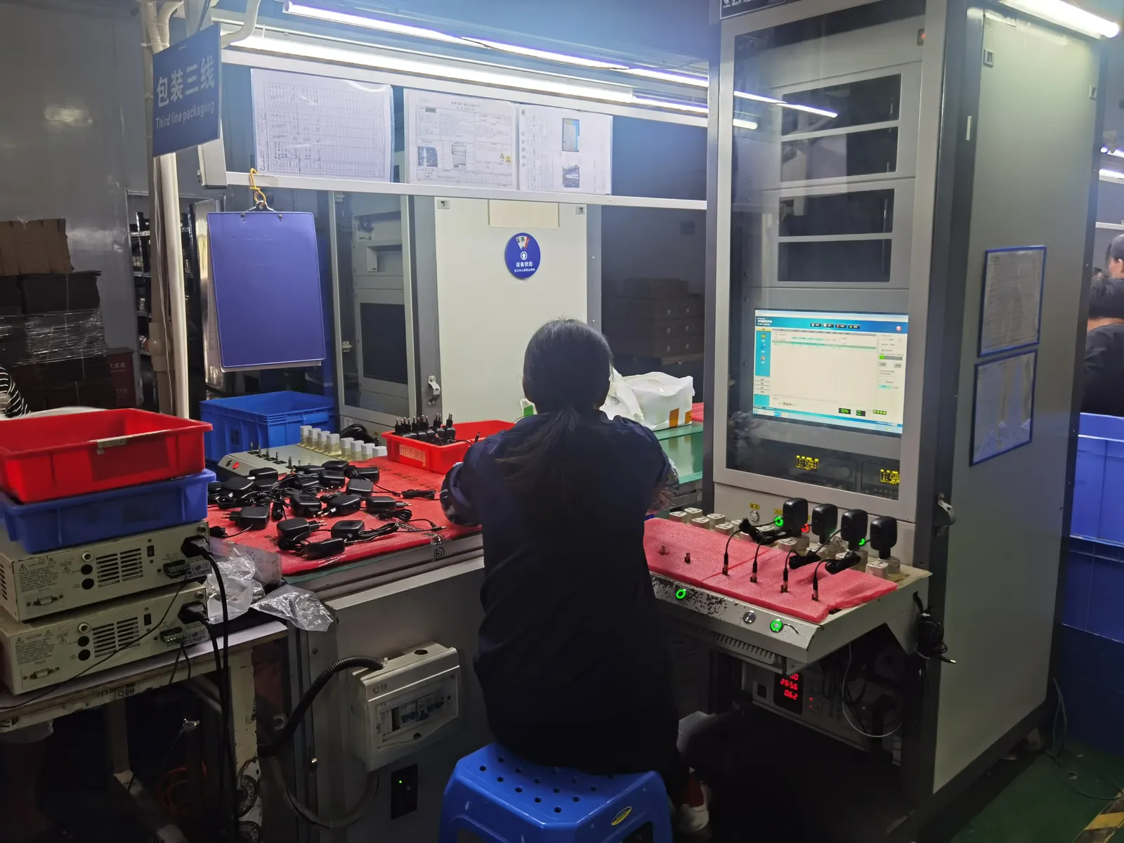
Four production gates map to the failure modes above: incoming inspection of critical components (capacitors, magnetics, ICs), 100% ATE functional testing of every finished unit under load, burn-in at load and elevated ambient so thermal and solder failures surface in the factory, and final inspection for mechanical and cosmetic quality. What the gates cannot catch is a design that was never rated for the application — which is why the specification conversation matters more than any single test. The methods are described step by step in how to test a power supply.
How the specification prevents them
Half the failure modes are prevented on paper before production starts: state the ambient range and derating expectations (thermal aging), the connector insertion cycles and pull force (wear), the input surge environment (surge), the humidity and coating requirement (corrosion), and the peak budget (overload). A factory that receives this specification can design against it — and a factory that cannot answer it has told you something. The full pre-production conversation is in our sample evaluation checklist.
Reading field returns like an engineer
When returns come back, treat them as data: open a sample of them, identify the failure mode for each, and log the pattern — connector vs capacitor vs solder tells you which layer owns the problem. A disciplined factory will do this analysis with you and feed it into change control; the five agreement clauses that make that cooperation mandatory are in our OEM agreement guide. Returns that are actually packaging damage, on the other hand, follow the shipping logic in our shipping guide.
Warranty and lifetime expectations
What is realistic to expect? A well-designed, well-built adapter running inside its derating curve typically serves 5–10 years, with electrolytic capacitor life usually setting the ceiling. Warranties of 1–3 years are standard; longer commitments come from factories with the burn-in and component discipline to back them. Ask for the capacitor life calculation at your operating temperature — it is the single most honest reliability number a supplier can give you, as discussed in our medical power supply guide.
Frequently asked questions
What is the most common power adapter failure mode?
Electrolytic capacitor aging in continuously loaded, warm environments — followed closely by connector and cable damage from mechanical abuse. Both are predictable and preventable at design stage.
How long should a power adapter last?
Five to ten years inside its derating curve, with capacitor life as the practical ceiling. Continuously overheated adapters can fail in a fraction of that time.
Why do failures spike in summer?
Ambient heat. Summer raises both the adapter’s own operating temperature and its aging rate — marginal units and marginal placements cross their thermal limits in the same weeks.
Can surge damage be prevented?
Reduced, not eliminated: specify the right input stage for the installation environment, and verify surge immunity in testing. No consumer adapter survives a direct lightning strike.
Does burn-in really catch failures?
It catches the infant-mortality band — factory escapes and weak components that fail in the first hours of load. It cannot catch aging failures, which is what derating and capacitor life calculations are for.
What is infant mortality?
The early-life failure band where manufacturing escapes and marginal components fail — typically the first weeks of use. Burn-in exists precisely to burn this band off before shipment.
Can we request failure analysis on returned units?
Yes, and you should: a structured returns analysis (mode, root cause, batch) is part of a serious quality relationship — put it in the agreement’s change-control and quality annex.
How does all this apply to specific device categories?
The modes are universal; the stress weighting changes. Mini PCs stress heat continuously, POS stresses printer peaks and public abuse, network gear stresses surge and unattended sites — the vertical guides on this blog (mini PC, POS, network) weight the same seven modes for their environments.
Sources
- IEC — 62368-1 safety standard family
- UL — Safety and reliability testing for power supplies
- IPC — Electronics assembly and soldering quality standards
Related on this blog: how to test a power supply, power adapter sample evaluation, mini PC power adapter OEM.