Cobot Power Supply: 24V or 48V, Stop Categories and the Documentation Safety Needs
Published: September 2026
Reading time: 12 min
Audience: cobot and mobile robot builders, machine integrators, control-cabinet designers and procurement teams specifying DC power for collaborative robot cells
By Han — Paiyi Power, an OEM/ODM power supply manufacturer building custom and modified-standard supplies from 5W to 240W, including industrially rated DC supplies with the reliability data that machine safety documentation requires.
Last updated: 21 September 2026.
Contents
Direct answer: what does a cobot power supply need?
A cobot power supply is specified in two layers. The functional layer is a 24V DC supply for most collaborative arms — 48V DC once the axis count, reach or payload grows into heavy industrial territory — sized with 30–50% headroom over the worst-case peak. The safety layer is what makes it different: it has to behave correctly when power is removed, and it has to come with the reliability data that a PL calculation needs.
Most selection guides stop at the first layer. They compare watts, price and protection features, and they are answering a question that was never the hard one. The hard question is what happens during a stop, and whether the numbers you can document are good enough to put in a safety file.
This guide covers both layers. For the wider industrial context see power supply solutions for robotics, AGV and AMR. At Paiyi Power we build from 200 pcs per model, with samples in about a week and first production in 5–6 weeks after approval.
Why a cobot is a safety problem before it is a power problem
A collaborative robot is defined by the fact that a person works next to it without a fence. That single design choice propagates all the way down to the power supply.
- The safety case is documented, not assumed. A collaborative cell needs a risk assessment, defined safety functions, a required performance level for each, and evidence that the architecture achieves it.
- The power supply is inside that architecture. It feeds the control circuits and the drives, so how it behaves when the safety system intervenes is part of the safety case rather than an incidental detail.
- Collaborative operation does not mean gentle motion. A power-and-force-limited arm still carries real kinetic energy, and the stop itself is a dynamic event the electrical system has to survive.
- Integrators absorb the consequences. If the supply’s documented reliability data cannot support the PL calculation, the integrator has to change the architecture or change the supply — late, and expensively.
That is why a cobot supply should be specified with the safety file open, not after it.
Cobot power supply: 24V or 48V?
The market has settled into two DC voltage levels, and the choice follows the mechanical design rather than preference.
| Voltage | Where it fits | Note |
|---|---|---|
| 24V DC | Most small collaborative arms, control circuits, sensors, end effectors | The default for cobots and the standard control-circuit voltage |
| 48V DC | Heavy industrial arms, multi-axis systems, larger mobile platforms | Halves current for the same power, which shrinks cable and loss |
The practical rule: most collaborative robots run on 24V, and you move to 48V when current, not voltage, becomes the constraint. Doubling the voltage halves the current, which matters once servo acceleration peaks start driving cable gauge and connector ratings.
IEC 60204-1: the electrical code that applies
Robots and their cells are machines, and machines are governed by the electrical code for machinery rather than by the generic safety standard for IT equipment.
- Control circuits at 24V DC. The standard expects control circuits to operate at 24V DC on an SELV or PELV basis, so that no hazardous voltage is brought to a panel or a teach pendant.
- Anything above the SELV boundary needs protection. Circuits above a defined voltage threshold must be enclosed or interlocked, which shapes how a supply and its wiring are laid out in the cabinet.
- Protective earth continuity is tested, not assumed. The requirement is a low-impedance connection — commonly quoted as a tenth of an ohm — between the protective conductor and every touchable conductive part.
- A lockable main disconnect is required. The machine needs a means of isolation that can be locked in the off position, which is where the supply sits in the topology.
The consequence for a power supply: the supply’s earth terminal, its fault behaviour and its insulation are all inside this code, not outside it.
Stop categories, and what they demand of the supply
This is the part that separates a cobot supply from an industrial supply, and it is decided by how power is removed rather than by how much power is delivered.
| Stop category | What happens | Implication for the supply |
|---|---|---|
| Category 0 | Immediate removal of power — an uncontrolled stop | Output capacitance determines how long the drives stay energised after the contactor opens |
| Category 1 | Controlled stop, then power removed once standstill is reached | The supply has to stay inside its regulation during a high-current deceleration |
| Category 2 | Controlled stop with power maintained | The supply keeps working, so its continuous rating and thermal margin govern |
An emergency stop must use category 0 or category 1, which means the supply’s behaviour during power removal is a design parameter rather than a side effect. Two consequences follow immediately, and both are routinely missed in selection guides.
- Too much capacitance is a problem, not a feature. A large output capacitance keeps the drives alive for milliseconds after the contactor opens, which can produce motion during what is supposed to be an uncontrolled stop.
- Too little capacitance is also a problem. A supply that collapses instantly cannot support a category 1 controlled stop, where the drives need to decelerate the arm under control before power goes away.
So the honest specification line is not “low ripple” alone. It is hold-up time and discharge behaviour at the output, stated as numbers.
Hold-up time: the parameter nobody specifies
This is the specification gap we see most often when a cobot cell is being documented, and it is worth stating plainly because it costs very little to fix at the design stage.
A DC supply holds energy in its output capacitors. When the safety system opens the contactor, that energy does not disappear — it continues to feed the drives until the capacitors discharge. The interval is short, but short is not zero, and in a machine that moves at speed, a few milliseconds of unexpected motion is a safety-relevant quantity rather than a rounding error.
- Ask for the measured value, not the topology. Output capacitance in microfarads, and the resulting hold-up time at the cell’s actual load current.
- Ask how the output behaves at removal. Whether the voltage decays smoothly or collapses, and whether any output continues to hold a residual charge.
- Match it to the stop category. A category 0 stop wants a predictable, adequately fast decay; a category 1 stop wants the supply to survive the controlled deceleration without dropping out early.
- Put it in the safety file. The stop-time measurement is part of the validation evidence, and the supply’s behaviour is part of what the measurement reflects.
Because this costs nothing extra to specify and is expensive to discover during validation, it belongs in the RFQ from the first enquiry.
Where the safety functions actually live
Modern collaborative cells place most safety functions inside the servo drive rather than in a contactor, and knowing where they live tells you what the supply is actually responsible for.
- Drive-integrated safety functions. Functions such as safe torque off and safe stop are implemented in the drive under the machinery safety-function standard for drive systems, so the motor is disabled without necessarily dropping the DC bus.
- Safe torque off underpins an uncontrolled stop. Because the drive removes torque itself, a fast decaying supply is not the only mechanism available — which changes how much capacitance is tolerable.
- Safe stop variants support controlled stops. A controlled stop with subsequent power removal needs the bus to remain within limits during deceleration, which is where the supply’s regulation and current capability matter.
- The consequence for the supply. Being inside a modern architecture means the supply must not undermine the drive’s safety function — through dropout during deceleration, unexpected behaviour at power removal, or injected noise on the control rails.
Ask the integrator which functions are implemented where. The answer changes the supply’s required behaviour more than the load calculation does.
PL and PLr: why MTBF is the wrong number
This is the point where a generic industrial supply stops being sufficient, and it is entirely about documentation rather than hardware.
Machine safety uses a required performance level derived from the risk assessment, typically a demanding one for interlocked safeguards and safety-related control functions. The achieved performance level is then calculated from the structure of the channel: its architecture category, the mean time to dangerous failure of each component, the diagnostic coverage, and the common cause failure measures.
- You cannot buy a performance level. It is a property of the whole architecture, verified by calculation and validated by testing — not a certificate attached to a component.
- A headline MTBF figure is not usable. A datasheet reliability number is usually quoted for general information, without the failure-mode split that a safety calculation requires.
- What the calculation needs. Mean time to dangerous failure per component, an indication of diagnostic coverage that the design can actually claim, and component-level service life where it exists.
- Why this matters commercially. If the supply cannot supply these numbers, the integrator must either treat it as a single-channel element with degrading consequences, or add redundancy, or change the supply. All three are worse than getting the numbers up front.
So the question to ask a supplier is not “what is your MTBF” but “can you provide component-level reliability data suitable for a safety calculation, and in what form”. A supplier who understands the difference will answer the second question without hesitating.
Peak current and dynamic response
The functional layer still matters, and it is where most selections go wrong in the ordinary way.
- Size on peak, not on average. Servo acceleration produces short current peaks well above the running load, and the supply has to hold regulation through them.
- Keep 30–50% headroom. A 30% margin is the working figure; 50% is appropriate for cells where the duty cycle is aggressive or the environment is hot.
- Check dynamic response, not just steady-state accuracy. A supply that recovers slowly from a load step will produce visible jitter and, in a collaborative cell, degraded motion quality that shows up in the application rather than the electrical measurements.
- Include the whole load. Controllers, sensors, safety devices, grippers and cabinet cooling all draw from the same supply, and the auxiliary loads are the ones that get forgotten.
Jitter and positioning error are frequently blamed on the robot or the drive tuning when the cause is a supply that cannot hold its output through repeated acceleration.
EMC in the industrial environment
Industrial EMC is not commercial EMC with a different label. The environment and therefore the requirements are different.
- Immunity is the harder half. An industrial environment contains drives, contactors, welding equipment and variable-frequency loads, so the immunity requirements are materially stricter than for office or residential equipment.
- Emission still matters. The supply must not disturb the machine’s own control and communication signals, which are often the very signals carrying safety information.
- Cabinet reality. Cable routing, screening and earth arrangements inside a control cabinet affect EMC performance as much as the supply’s own filter, which is why installation instructions belong in the documentation.
- Test against the industrial standards. Ask which immunity and emission standards the unit was assessed against, and confirm they are the industrial ones rather than the generic commercial set.
A supply that passes commercial EMC and sits in a cabinet next to three servo drives is a false sense of security.
Protective earth and cables that move
Robots are among the few machines where the cable itself is a moving part, and that changes what reliability means for the connections.
- Earth continuity under flex. The protective conductor requirement applies to the arm, the controller and the cabinet, and it has to survive continuous flexing rather than a single installation test.
- Strain relief and bend radius. Cable assemblies on a moving axis fail at the terminations, and a documented bend radius is what allows a designer to respect them.
- Shielding and earth loops. Screened motor cables and earth bonding arrangements interact; getting them wrong shows up as intermittent faults that are extremely expensive to diagnose in the field.
- Terminal quality. A supply’s output terminals and the way they are specified — ferrules, torque, current margin — matter more in a vibrating cabinet than in a static installation.
The electrical code’s earth-continuity requirement is a useful reminder that in robotics the wiring is not a static item after commissioning.
Redundancy for cells that cannot stop
Some installations cannot tolerate an unplanned stop at all, and that requirement is what drives dual-supply topologies.
- When redundancy is justified. Continuous production lines, cells feeding a process that cannot be restarted cheaply, and installations where a stalled robot creates a hazard rather than merely a delay.
- What redundancy costs. A second unit, a decoupling arrangement and a monitoring scheme that detects a failed supply and reports it, because an unnoticed failure leaves you with no redundancy at all.
- Redundancy is not a safety function by itself. Availability and safety are different objectives, and adding a second supply does not satisfy a safety requirement that demands a specific channel architecture.
- Decide it early. Redundancy changes the cabinet, the wiring and the cost, so it belongs in the concept phase rather than in a retrofitted fix.
The honest framing: redundancy buys uptime. Safety is achieved through the safety functions and their validation, and conflating the two is how projects end up with neither.
What changed in the standards, and in Europe
Two developments are worth knowing if your cobot programme has a two-year horizon, because both land inside it.
- The robot safety standards were revised. The 2025 editions of the robot and robot-system standards folded the bulk of the former collaborative-technical-specification content into the normative standards, and tightened requirements around safety-rated functions. Behaving to the older edition is no longer the safest planning assumption.
- The European legal framework is changing. The machinery directive is being replaced by a machinery regulation, which applies from 20 January 2027. Compliance is not a one-off exercise for a programme that spans that date.
- Integration is where the risk sits. The robot as a product and the robot as an installed cell are assessed against different parts of the same standard family, and the cell is where most compliance work actually happens.
- Verify versions before filing. Standards get revised and harmonised lists change; confirm the edition you are filing against rather than the one in an old project folder.
We are explicit about our own position: we build to the applicable safety and power specifications, and certification status varies by model and market. We do not claim approvals we do not hold for every model, and the certificates we hold are CE, CB, FCC and ISO 9001. For a robot cell, the machine-level conformity is the integrator’s responsibility, and that is precisely why the supply’s documentation has to be good enough to hand over.
Documentation to ask for
For a cobot programme the documentation is not paperwork; it is an input to somebody else’s legal obligation. Ask for these before price.
- Component-level reliability data suitable for a safety calculation, including the failure-mode split rather than a single MTBF figure.
- Output capacitance, hold-up time and discharge behaviour at the cell’s load current.
- Immunity and emission standards actually assessed, confirmed as the industrial set.
- Peak current capability and dynamic response data, with the test conditions stated.
- Thermal derating curve for the real cabinet temperature, not a benchtop figure.
- Written change control, because a component substitution invalidates a safety calculation as readily as it invalidates a certificate.
Our sample evaluation checklist covers how to test the first article against these lines, and the OEM agreement guide covers the change-control terms that keep them true in production.
Cobot power specification table
| Parameter | Typical for collaborative robot cells | Note |
|---|---|---|
| Output voltage | 24V DC for most cobots; 48V for heavy or multi-axis | Higher voltage halves current and cable loss |
| Sizing | Worst-case peak plus 30–50% headroom | Average sizing shows up as jitter |
| Control circuits | 24V DC on an SELV or PELV basis | Per the machinery electrical code |
| Hold-up and discharge | Stated output capacitance, hold-up time and decay behaviour | Directly affects what a stop category can rely on |
| Reliability data | Component-level data for a safety calculation | A headline MTBF figure is not usable |
| EMC | Industrial immunity and emission standards | Not the commercial set |
| Earth continuity | Low-impedance protective bonding through moving cables | Must survive continuous flexing |
| Thermal | Derating curve for real cabinet temperature | Cabinet interiors run hotter than the room |
| Confidentiality | Written change control and confidentiality terms | Robot programmes carry IP; see the OEM agreement guide |
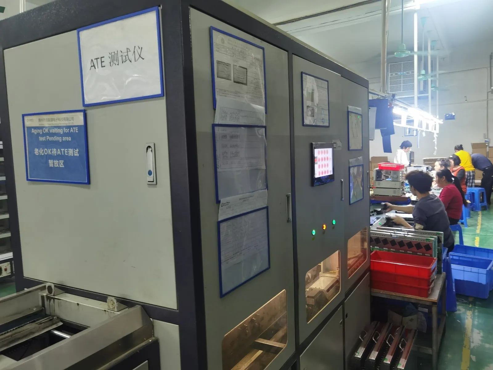
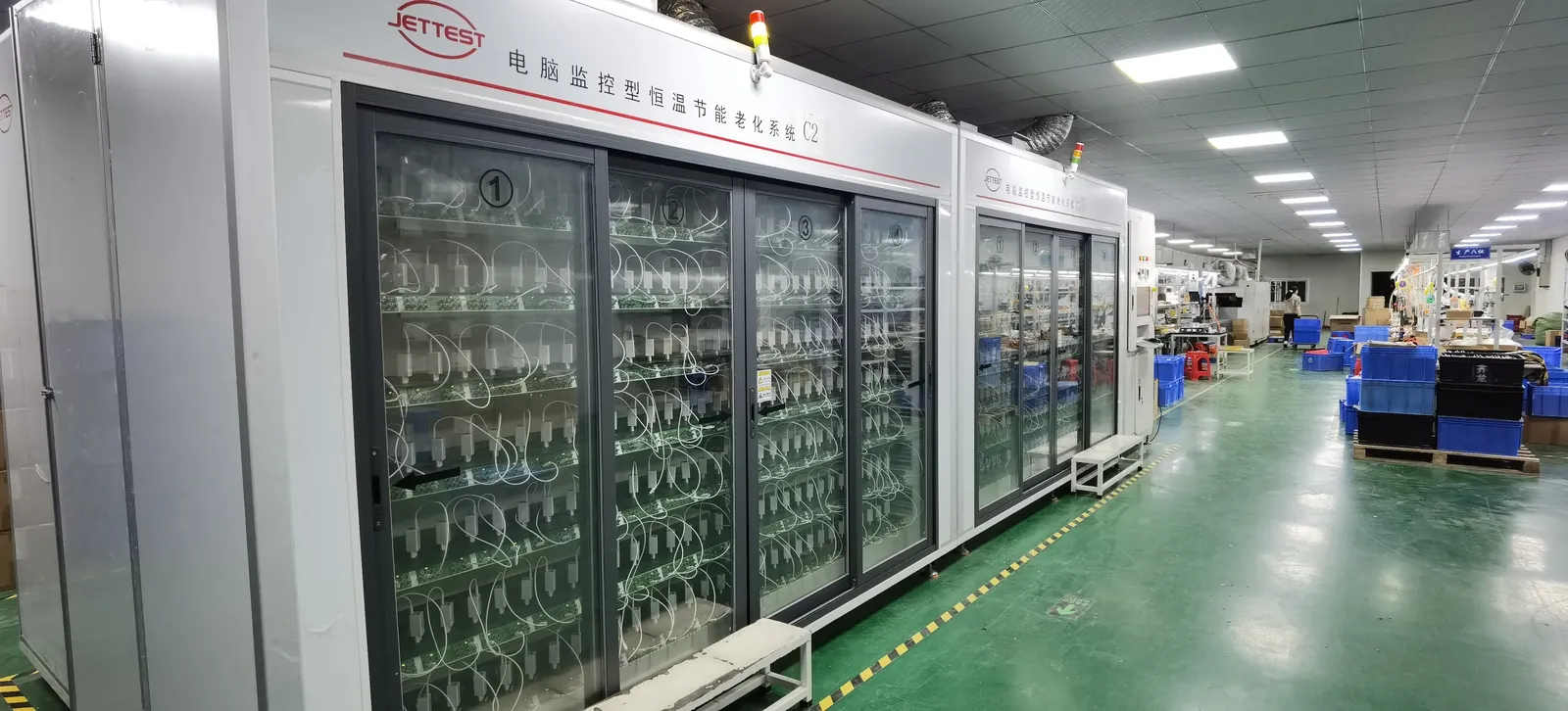
| Reliability practice | 100% ATE + burn-in before shipment | Every unit, not a sample |
Frequently asked questions
What voltage does a cobot power supply use?
Most collaborative robots run on 24V DC; heavy industrial arms and multi-axis systems move to 48V DC. The choice follows current rather than preference: doubling the voltage halves the current, which reduces cable gauge, loss and connector stress once servo acceleration peaks become the constraint.
Which safety standard applies to a cobot power supply?
The machinery electrical code, not the generic IT equipment standard. Control circuits are expected at 24V DC on an SELV or PELV basis, protective bonding is verified to a low impedance, and a lockable main disconnect is required — all of which place the supply inside the machine’s electrical architecture.
Why does output capacitance matter for safety?
Because it determines how long the drives stay energised after the safety system removes power. A large capacitance can produce motion during a stop that is supposed to be uncontrolled; too little capacitance cannot support a controlled stop. Ask for the value and the hold-up time at your load current.
What is the difference between a category 0 and category 1 stop?
Category 0 removes power immediately — an uncontrolled stop; category 1 performs a controlled stop and then removes power. Emergency stops must be one of these two, which is why the supply’s behaviour at power removal is a design parameter rather than an incidental detail.
Can I just use an industrial power supply with a good MTBF?
Usually not, because a headline MTBF figure cannot be used in a safety calculation. The calculation needs mean time to dangerous failure per component and the failure-mode split, so ask for component-level reliability data suitable for a safety file rather than a single reliability number.
How much power headroom should I allow?
Thirty percent over the worst-case peak as a working figure, and fifty percent for aggressive duty cycles or hot cabinets. Size on the peak created by servo acceleration, not on the average, and remember that controllers, sensors, grippers and cabinet cooling all draw from the same supply.
Does EMC matter differently in a robot cell?
Yes — the immunity requirement is materially stricter in an industrial environment than in a commercial one. A supply assessed against the commercial standards and then installed beside servo drives is a false sense of security; confirm the industrial immunity and emission standards were used.
Do I need a redundant power supply?
Only if an unplanned stop is genuinely unacceptable — redundancy buys uptime, not safety. Safety is achieved through the safety functions and their validation. If you do add redundancy, include monitoring, because an unnoticed failure leaves you with none.
What MOQ and lead time apply for cobot power supplies?
From 200 pcs per model at Paiyi Power, with samples in about a week and first production 5–6 weeks after sample approval. We build to the applicable safety and power specifications and can supply the reliability data and documentation your safety file needs; certification status varies by model and market, and we do not claim approvals we do not hold. See also industrial power supply applications.
Sources
- IEC — 60204-1 machine electrical equipment, 61800-5-2 drive safety, 61000-6-2 and 61000-6-4 industrial EMC
- ISO — 10218-1/-2 robot safety, ISO 13849-1 functional safety, ISO 12100 risk assessment
- A3 — Association for Advancing Automation, robotics and industrial safety resources
- UL — safety certification for power supplies and industrial equipment
- EUR-Lex — machinery directive and the machinery regulation applying from January 2027
Related on this blog: power supply solutions for robotics, AGV and AMR, industrial power supply applications, industrial sensor power supply adapter, BMS board power supply.