
AGV Charging Station OEM: 24V and 48V Dock Architecture, Opportunity Charging and What Industrial Buyers Verify
Published: September 2026
Reading time: 12 min
Audience: AGV and AMR builders, warehouse automation integrators, and procurement teams specifying automatic charging infrastructure for mobile robots
By Han — Paiyi Power, an OEM/ODM power supply manufacturer building external supplies from 5W to 240W and engineering higher-power charging stages per project, including the auxiliary and control rails inside a charging station.
Last updated: 21 September 2026.
Contents
Direct answer: what does an AGV charging station need?
An AGV charging station is a kilowatt-class DC charging product, not an adapter. It converts mains input to a pack voltage — commonly 24V or 48V — at currents from ten to several hundred amps, and it adds three things a plain charger does not have: automatic coupling, communication with the robot, and an auxiliary power rail that keeps the station’s own control electronics alive.
The last of those three is the one most often specified badly, and it is the one that matters most to a programme that cannot afford an unplanned stop. This article covers the whole architecture and then, at the end, the evidence an industrial buyer looks for before committing — because in this category that is usually the real gate, not the price.
For the robot’s own power architecture see our robotics, AGV and AMR power guide, and for the safety-architecture view see cobot power supply.
The power classes, stated plainly
This category spans a very wide power range, and knowing which class you are actually buying prevents a year of mismatched conversations.
| Class | Typical output | Where it sits |
|---|---|---|
| Small service and cleaning robots | 24V at roughly 5 to 20A | Light payloads, long idle windows, simple docks |
| Warehouse AMR and light AGV | 24V or 48V at 20 to 50A | The volume part of the market, roughly 500W to 2.5kW |
| Heavy AGV and forklift | 24V to 96V at 50 to 200A | 3kW to 20kW, often three-phase input |
| Inductive and wireless | 600W to several kW, up to very high current | No exposed contacts, tolerant of large misalignment |
The honest reading: the middle two rows are where most programmes live, and both are well above the range of an external power brick. A charging station is a power electronics product in its own right, with its own certification route, and it should be scoped as one.
Why the station is a kilowatt product
Understanding why the numbers land where they do makes the specification much easier to write. Three forces push the power up.
- Duty cycle. A robot that works two shifts cannot spend four hours charging. The charger’s power is set by how much energy the robot needs divided by how long it can afford to be off the floor.
- Opportunity charging. If a fleet tops up in short windows instead of charging fully, every one of those windows has to deliver meaningful energy quickly, which raises current rather than reducing it.
- Fleet economics. Charging infrastructure is bought per robot but justified per fleet. A slower station means more robots or more stations, and the arithmetic usually favours more power.
That is why the market has settled in the hundreds of watts to several kilowatts, with forced cooling, and why an external supply of the kind used for cameras or access control is not the right comparison.
The architecture: from mains to contacts
A charging station is a chain, and each stage has its own requirements and its own failure modes.
- Mains input and protection. Single-phase on smaller units, three-phase on large ones, with input protection, inrush management and a disconnect that can be locked off.
- Power factor correction. A kilowatt-class load draws a current waveform that has to be corrected; power factor is a specification line and often a tariff requirement.
- Isolated DC conversion. The conversion stage that produces the pack voltage, with isolation between mains and output, and the thermal path designed for continuous operation rather than peaks.
- Charge control. The constant-current, constant-voltage stage that actually charges the pack, with termination and the protections that go with it.
- Output switching and coupling. The contactor or semiconductor switch, the contact block or inductive coupler, and the logic that decides when it is safe to energise the output.
- Auxiliary rails. The small 12V or 24V supply that runs the station’s own controller, contactor drive, sensors and communication — covered in the next section.
The practical point: a charging station contains a power supply, but it is not a power supply. The conversion stage is one link, and the value of a supplier in this category is often in understanding the links around it.
Auxiliary and control power: the part specified badly
Every charging station needs a small regulated rail to run its own electronics, and it is routinely left out of the specification until late.
- What it powers. The station’s controller, the contactor or relay drive, safety monitoring, indicator and status lights, and the communication module. Typically 12V or 24V at 3 to 5A.
- Why it is easy to miss. It is small relative to the main output, so it does not look significant in a load table — right up to the point where it browns out during a main-output transient and takes the station’s logic with it.
- Why it is demanding. It must stay inside regulation while a multi-hundred-amp output stage switches, which is an EMC and transient problem rather than a power problem.
- Why it is worth specifying early. An auxiliary rail designed alongside the main conversion is straightforward. One added afterwards to a finished station is a redesign of the control architecture.
This rail is also the part of the station a conventional external power supply manufacturer is best placed to build, because it is the same discipline as any other regulated DC output — with the difference that the environment around it is electrically hostile.
Opportunity charging changes the profile
Opportunity charging is now the default strategy in most automated facilities, and it changes what the charging hardware has to tolerate.
- The battery lives in a narrow band. Instead of a daily deep cycle, the pack sits between roughly half and full, topping up whenever the robot is idle. That extends cycle life but makes the charger work far more often.
- More cycles, more switching. Every top-up is a full start-up sequence: coupling, handshake, contactor close, current ramp, taper, termination, contactor open. Hardware designed for one long daily charge sees many short ones instead.
- Every start-up is a stress event. Inrush, contactor wear and the thermal cycling of the conversion stage are all driven by the number of cycles, not the energy delivered.
- So the reliability specification changes. Component life in this application is set by cycle count, and that is the number to ask about rather than operating hours alone.
A station specified for cycle count rather than for hours — or for energy — is the one that survives a real fleet.
Charging a partially charged pack
Opportunity charging also means the charger almost never starts from empty, and that has a direct consequence for the charge profile.
- A partially charged pack is already in the constant-voltage region. Its voltage is close to full, so the charger spends more of its time in the taper than a full-charge cycle would suggest.
- Current accuracy matters more at low current. In the taper the charger is regulating a small current on a large output stage, which is exactly where measurement and loop design are hardest.
- Termination must be reliable at partial charge. A charger that struggles to detect completion when started near full will either undercharge or fail to stop, and the second is a safety problem.
- The BMS is the other half of the conversation. Most robots manage charging through the pack’s management system, so the charger and the BMS have to agree on targets and interlocks. See BMS board power supply for that side.
This is why a charging station is specified against a battery and a BMS rather than against a voltage and a current alone.
Contact charging: alignment, wear and safety
Contact-based charging remains the most common approach, and its reliability is mostly mechanical.
- Contact blocks are rated for serious current. High-current brush blocks and heavy-duty connectors are the norm, and the rating is a specification line rather than an accessory choice.
- Alignment tolerance decides uptime. The station has to accept the robot’s real docking accuracy, not its published accuracy, and the tolerance should be stated in millimetres in three axes.
- Wear is a designed-in number. Contact life is quoted in tens of thousands of cycles in this market, and it is set by contact material, spring pressure and the alignment tolerance you specified.
- Contacts must not be live until the handshake completes. A station that presents voltage to exposed contacts has a safety problem regardless of how well it charges; the sequencing and detection logic is a core requirement.
- Dirt and moisture matter. Warehouse floors are dusty and sometimes wet, and the contact area is where that becomes an electrical problem.
For a station, the mechanical and safety design is at least as demanding as the conversion stage — a useful thing to remember when comparing quotes.
Inductive charging: what changes
Inductive charging removes the exposed contacts and the alignment problem, at the cost of other constraints.
- No exposed conductors. Nothing is energised on the surface, which removes the contact-safety problem and much of the wear.
- Large misalignment tolerance. Wireless pads commonly accept offsets in the order of tens of millimetres and a working gap measured in tens of millimetres, which suits robots that dock roughly.
- Efficiency is lower than a contact connection. Coupling losses are real, and they show up as heat in the pad and in the robot.
- Protection and environment. Sealed designs are common in this segment, which suits cold-chain, outdoor and washdown applications.
If you are evaluating inductive charging, the questions to ask are coupling efficiency at your real gap and offset, thermal behaviour at that efficiency, and the protection rating of both halves.
Communication with the fleet
A charging station is a networked device, and the interface is often as important as the power stage.
- Fieldbus to the robot. CAN and RS485 are the common interfaces for the charge handshake, with protocol documentation that the robot integrator has to implement against.
- Uplink to the fleet system. Ethernet, Wi-Fi or cellular to report state, energy delivered, faults and availability to a fleet management system.
- Why it matters commercially. A station that cannot report is a blind spot in a fleet that is otherwise fully monitored, and operators increasingly buy on visibility rather than on watts.
- Protocol ownership is a trap. Proprietary handshakes lock the customer in, and are worth avoiding on both sides of the table.
Write the interface into the requirement list. It is the part of a charging station that is hardest to change after the fleet has been commissioned.
Standards that apply
Several standards meet in this product, and each one covers a different layer.
- The converter itself. Power electronic converter systems have their own safety standard, and it is a different document from the general IT safety standard used for external adapters.
- The mobile machine. Driverless industrial trucks and industrial mobile robots are covered by machine-specific safety standards, which address safety-rated speed, protective fields that scale with speed, and stopping performance under load.
- The battery. Industrial lithium cells and batteries have their own safety standard, separate from the consumer and vehicle standards.
- The electrical equipment of the machine. The general machinery electrical standard governs the control circuits, protective bonding and isolation arrangements of the station as part of a machine.
Because four different layers apply, it is worth writing down which party owns which filing before the project starts. In this category that single conversation prevents the most common late-stage dispute.
Thermal and environmental reality
Charging infrastructure lives in the least pleasant part of the building, and the specification should follow.
- Ambient is high and variable. Industrial equipment of this class commonly works across roughly 0 to 55 °C with intelligent derating above about 50 °C, and the derating curve is the number that matters.
- Forced cooling is normal above a certain power. That means airflow, filters and dust, and a maintenance interval that has to be documented or reliability suffers quietly.
- Ingress protection varies by site. Warehouse floors are dustier than the specification usually assumes, and outdoor or cold-chain sites need genuinely sealed units.
- Serviceability is a design requirement. A station that cannot be serviced without taking down a charging position is a station that will be left broken.
In a facility running 24 hours, the cost of an unavailable charging position is usually far higher than the cost of the station, which is why maintainability belongs in the requirement list.
What industrial buyers verify before they commit
This is the section worth reading twice if you are a supplier new to this class of product, because capability and credibility are two different gates.
Buyers of kilowatt-class charging infrastructure are usually integrators with their own customer obligations. They are not primarily buying power electronics; they are buying the ability to promise a customer that a fleet will keep running. That changes what they look for.
- Certification for the actual product class. Not a certificate for an adapter that shares a DNA, but evidence against the converter safety standard for this kind of equipment, for the model they are buying.
- Thermal validation at real ambient. A test report showing sustained output at the temperature of the actual installation, not a bench figure at 25 °C.
- Reliability data they can use. Cycle-count expectations for the contact interface, component-level reliability information, and the assumptions behind both.
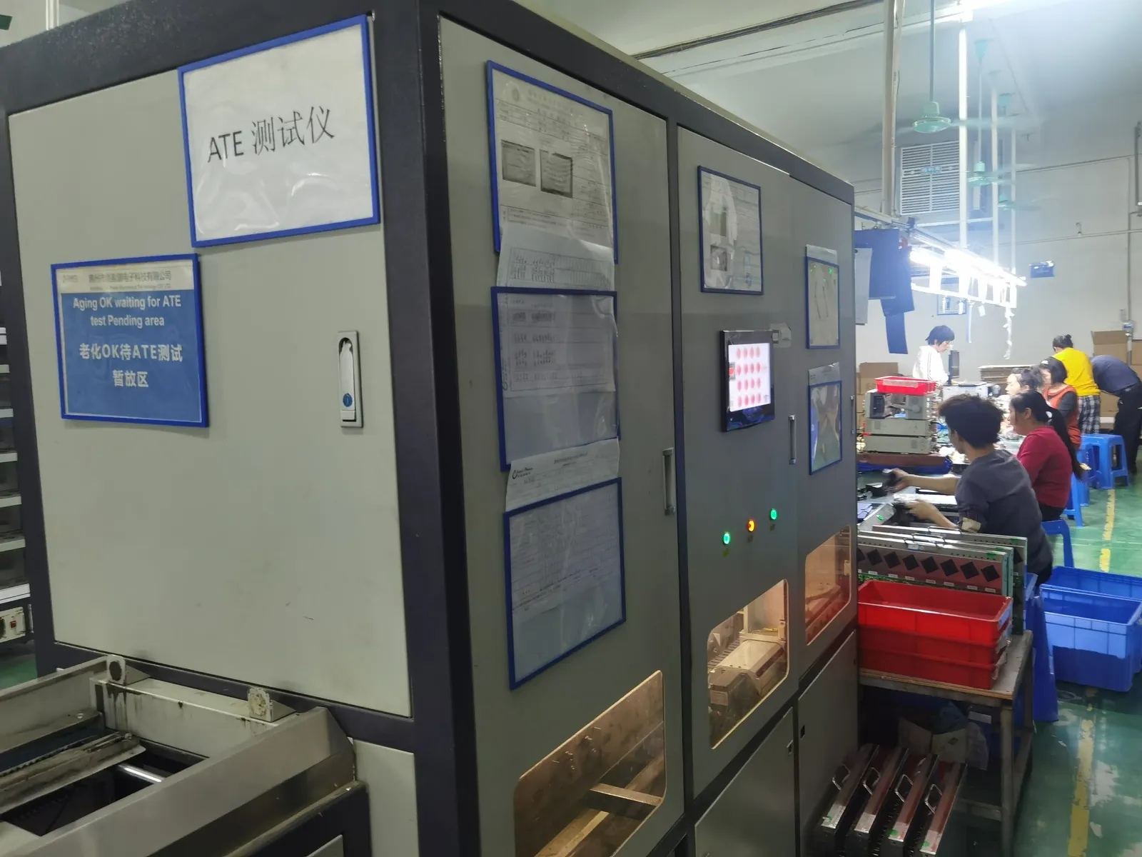
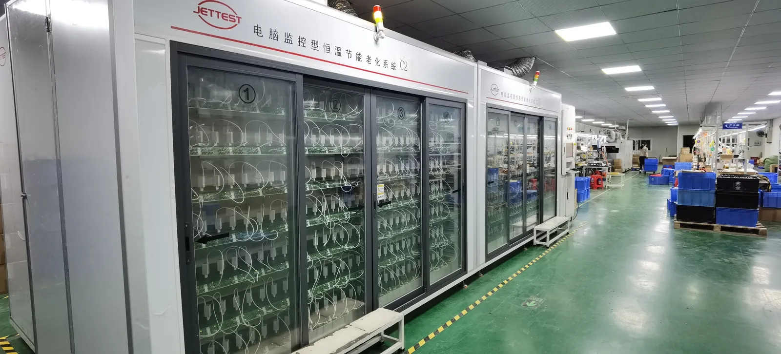
- Manufacturing process evidence. How units are tested before shipment, what the burn-in profile is, and what happens to a unit that fails — a supplier who can show a 100% test regime answers a question that a datasheet cannot.
- Reference installations. This is the hardest gate and the honest bottleneck: a buyer with a live facility will ask who else is running this product, and no amount of specification substitutes for an answer.
- Written change control. Because a substitution inside a converter can invalidate the buyer’s own system certification, not just a specification.
The practical consequence for a supplier entering this class: the first project is a credibility project, not a revenue project. It is won by being specific about which evidence exists and which does not, agreeing a qualification plan in writing, and delivering the first installation as if the whole relationship depends on it — because it does. Suppliers who claim a class they cannot evidence rarely get the second conversation, and they often do not get the first project finished either.
Our own position is deliberately plain: we build external supplies as a standard range and engineer higher-power charging stages per project, including the auxiliary and control rails inside a station. We would rather agree a qualification plan than overstate a reference list, and we would rather tell you which evidence we have than be found out later.
What to put in the RFQ
These lines are what a charging-station supplier needs in order to quote something that can actually be built and certified.
- The robot’s energy requirement — pack voltage, capacity, and the charge window the duty cycle allows.
- The charging strategy — full charge, opportunity charging, or both — because it sets the cycle count the hardware must survive.
- Coupling method — contact block, inductive pad or connector — and the alignment tolerance it has to accept.
- The auxiliary rail — voltage, current and what it powers.
- The interface — fieldbus to the robot and uplink to the fleet system, with protocol expectations.
- Environment — ambient range, ingress protection and the dust and moisture reality of the site.
- Certification ownership — which party files which layer, in writing.
- Serviceability — what has to be replaceable in the field and in what time.
Our sample evaluation checklist and the OEM agreement guide cover how to hold these points through production.
AGV charging station OEM specification table
| Parameter | Typical for AGV and AMR charging stations | Note |
|---|---|---|
| Output voltage | 24V or 48V typical; up to 96V on heavy platforms | Set by the pack, not chosen for convenience |
| Output current | 10A to 50A in the volume class; 50A to 200A heavy | Sets charge time against the duty cycle |
| Power class | Roughly 500W to 2.5kW mainstream; 3kW to 20kW heavy | Well above an external power supply class |
| Input | Single-phase on smaller units; three-phase on large ones | Power factor correction is a specification line |
| Auxiliary rail | 12V or 24V at around 3 to 5A for the station’s own control | Must hold regulation through main-output transients |
| Charging strategy | Opportunity charging dominant; many short cycles per day | Reliability is set by cycle count, not hours |
| Coupling | Contact blocks rated 100A to 200A, or an inductive pad | Contacts must not be live before the handshake |
| Alignment tolerance | Stated in millimetres in three axes, against real docking accuracy | Decides uptime more than the electrical spec does |
| Communication | CAN or RS485 to the robot; Ethernet, Wi-Fi or cellular uplink | Hardest item to change after commissioning |
| Environment | Around 0 to 55 °C with derating above 50 °C; IP54 to IP67 | Forced cooling brings filters and a service interval |
Frequently asked questions
What power does an AGV charging station need?
It depends on the class: small service robots charge at 24V and roughly 5 to 20A, warehouse AMRs and light AGVs at 24V or 48V and 20 to 50A, and heavy AGVs and forklifts from 50A upward. That puts mainstream stations in the several-hundred-watt to several-kilowatt range, which is a different product class from an external adapter.
Why is the power so much higher than a robot’s average draw?
Because charging power is set by the charge window, not by average consumption. A robot that works two shifts cannot spend half a day charging, and opportunity charging compresses the same energy into short, frequent windows — which raises current rather than reducing it.
Is an AGV charging station just a big power supply?
No — it contains a power supply, but it adds automatic coupling, communication with the robot, and an auxiliary rail for its own control electronics. The conversion stage is one link in the chain, and the stages around it are where reliability is usually won or lost.
What is the auxiliary power output for?
It runs the station’s own controller, contactor drive, safety monitoring, status lights and communication module — typically 12V or 24V at 3 to 5A. It is small enough to be overlooked and important enough that a brown-out takes the station’s logic with it, so it must hold regulation through main-output transients.
Why does opportunity charging stress the hardware more?
Because it multiplies cycle count. Instead of one long daily charge, the station runs many short ones, and every start-up brings inrush, contactor wear and thermal cycling. Component life in this application is set by cycles, so ask for cycle-count expectations alongside operating hours.
Contact or inductive charging?
Contact blocks are simpler and more efficient and are rated for very high current; inductive pads remove exposed contacts and tolerate large misalignment at the cost of coupling losses. Ask about efficiency at your real gap and offset, and about the protection rating of both halves.
Which standards apply to a charging station?
Several layers at once: the safety standard for power electronic converter systems, the machine-specific safety standard for driverless industrial trucks and mobile robots, the safety standard for industrial lithium batteries, and the general machinery electrical standard for the station’s control circuits. Agree in writing which party files which layer.
What do industrial buyers ask for before committing?
Certification for the actual product class, thermal validation at real ambient, usable reliability data including cycle counts, evidence of the manufacturing test regime, reference installations, and written change control. Reference installations are the hardest gate, which is why the first project in this class is a credibility project rather than a revenue one.
What MOQ and lead time apply for charging station power stages?
Our standard external supplies run from 200 pcs per model at Paiyi Power, with samples in about a week and first production 5–6 weeks after approval. Higher-power charging stages, including the auxiliary and control rails inside a station, are engineered per project with an agreed qualification and certification plan rather than priced from a catalogue. We state plainly which evidence we hold and which we do not.
Sources
- IEC — 62477 power electronic converter systems safety, 60204-1 machine electrical equipment, 62619 industrial lithium battery safety
- ISO — 3691-4 driverless industrial trucks, and machine safety standards for industrial mobile robots
- UL — safety certification for power conversion equipment and battery systems
- IEC — 62368-1 safety standard applicable to the auxiliary supply inside the station
- A3 — Association for Advancing Automation, resources on mobile robot deployment and safety
Related on this blog: power supply solutions for robotics, AGV and AMR, cobot power supply, BMS board power supply, portable power station charger OEM.