
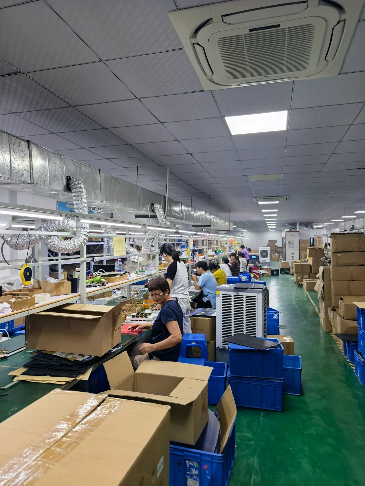
MOOP vs MOPP: Isolation, Leakage and Creepage in Medical Power Supplies
Published: September 2026
Reading time: 12 min
Audience: medical device engineers, regulatory and quality teams, and procurement specialists specifying the isolation level of a power supply inside a regulated medical device
By Han — Paiyi Power, an OEM/ODM power supply manufacturer building custom and modified-standard supplies to IEC 60601-1 design requirements, including low-leakage and 2×MOPP isolation builds.
Last updated: 21 September 2026.
Contents
Direct answer: what is the difference between MOOP and MOPP?
MOOP means Means of Operator Protection and protects the clinician; MOPP means Means of Patient Protection and protects the patient through the applied part. MOOP is the lighter requirement, MOPP is the stricter one, and the isolation level you need follows from the applied part classification rather than from the product’s marketing category.
The practical target for anything with a patient connection is 2×MOPP between mains and the secondary, commonly implemented as a dielectric withstand of around 4000 V AC with roughly 8 mm of creepage and 4 mm of clearance at typical working voltages.
But before you write those numbers into a specification, there is one thing worth understanding, because it is where most programmes lose time: an isolation rating and a leakage current limit are two different requirements, and satisfying the first does not give you the second. A supply can carry a genuine 2×MOPP rating and still fail a cardiac-class leakage limit. This article explains both.
For the wider selection context see custom medical power supply selection.
Where the two terms come from
Both terms come from the general safety standard for medical electrical equipment, and both describe a means of protection rather than a type of product.
- MOOP — operator protection. It protects the person using the equipment: a nurse, a technician, a clinician. The reasoning is that the operator is conscious, standing, and not electrically connected to the patient, so the tolerable exposure is closer to that of ordinary professional equipment.
- MOPP — patient protection. It protects the patient, and the assumption behind it is much more severe: the patient may be unconscious, may have reduced skin resistance, may be connected through electrodes, or may be connected to the heart itself.
- “Means” is the operative word. A means of protection is a barrier — a layer of insulation, a distance, an isolation component — not a certificate or a product label. Two means are two independent barriers.
- More than one of each can be required. The standard family uses multiples such as 1×MOPP and 2×MOPP, and a device may need both MOOP and MOPP barriers in different places at the same time.
That last point is the one most often missed: an equipment enclosure facing the operator is a MOOP question, while the circuit touching the patient is a MOPP question — in the same product.
The requirements, side by side
The figures below are the ones commonly used in the industry to describe each level. Read the next section before treating any of them as a specification.
| Level | Protects | Typical dielectric withstand | Typical creepage / clearance |
|---|---|---|---|
| 1×MOOP | Operator | Around 1500 V AC | Roughly 2.5 mm / 1.5–2 mm |
| 2×MOOP | Operator | Around 3000 V AC | Roughly 5 mm / 3–4 mm |
| 1×MOPP | Patient | Around 1500 V AC | Roughly 4 mm / 2.5 mm |
| 2×MOPP | Patient | Around 4000 V AC | Roughly 8 mm / 4 mm |
Two observations that matter commercially. First, 1×MOPP is not the same as 2×MOOP — the dielectric figures look similar, but the patient-protection requirement carries stricter leakage limits, which is the harder half of the problem. Second, 2×MOPP is a construction, not a component: you cannot buy it as a single part number any more than you can buy a performance level for a machine safety function.
The number people get wrong
A very common specification line reads simply “8 mm creepage for 2×MOPP”. It is a useful rule of thumb and a dangerous absolute, and it is worth understanding why.
Creepage and clearance are not fixed constants. They are read from tables whose values depend on at least three variables:
- Working voltage. The distance requirement rises with the voltage across the barrier, so a low-voltage secondary is not the same problem as a high-voltage rail.
- Material group. How readily the insulation surface tracks under contamination depends on the material, which is why the same design can comply in one laminate and fail in another.
- Pollution degree. The assumed contamination of the environment changes the required distance, and a device used in a clean clinical setting is not the same case as one used in a workshop or at home.
The honest consequence: the governing values are those in the standard’s tables for your actual working voltage, material and environment — and they are confirmed in your own test report. Treating “8 mm” as universal is how a design passes a checklist and fails a review.
What the rule of thumb is genuinely good for is definition: it tells a supplier what kind of construction you are asking for. What it is not good for is replacing the calculation.
Working backwards from the applied part
In practice you do not choose an isolation level first. You identify the applied part, and the isolation level follows.
| Applied part | What it means | Isolation typically required |
|---|---|---|
| Type B | No direct electrical contact, or brief non-conductive contact | 1×MOPP is usually sufficient |
| Type BF | Electrically connected to the patient but isolated, not the heart | 2×MOPP |
| Type CF | Possible direct cardiac contact | 2×MOPP, plus the strictest leakage limit |
This is where a specification becomes useful. Writing “we need a 2×MOPP supply” is a construction requirement; writing “BF applied part, 2×MOPP barrier input to output, plus a separate 1×MOPP barrier from output to earth” is a design brief that a supplier can actually engineer against.
Note the second barrier in that example. Patient-contact equipment frequently needs both: a heavy barrier from mains to the secondary, and a lighter but still real barrier from the secondary to anything the operator or earth can touch.
Leakage current: the limits that decide the design
Isolation withstand is a survivability requirement. Leakage current is a continuous-flow requirement, and it is the one that constrains real designs.
| Leakage path | Normal condition | Single fault condition |
|---|---|---|
| Earth leakage (Class I) | 5 mA | 10 mA |
| Touch / enclosure current | 100 µA | 500 µA |
| Patient leakage, Type B and BF | 100 µA | 500 µA |
| Patient leakage, Type CF | 10 µA | 50 µA |
Indicative figures for orientation; the governing limits come from the edition of the standard you file to and must be read from your own test report.
Read the CF row twice. Ten microamps is roughly a hundred times tighter than the earth leakage figure, and it is the number that decides whether a medical supply programme is straightforward or difficult. A device that touches the heart has almost no tolerance for anything the power supply couples across its isolation barrier.
This is also why the applied part classification, not the product category, drives the purchasing decision. Two products that both look like “medical power supplies” can differ by an order of magnitude in the difficulty of the design.
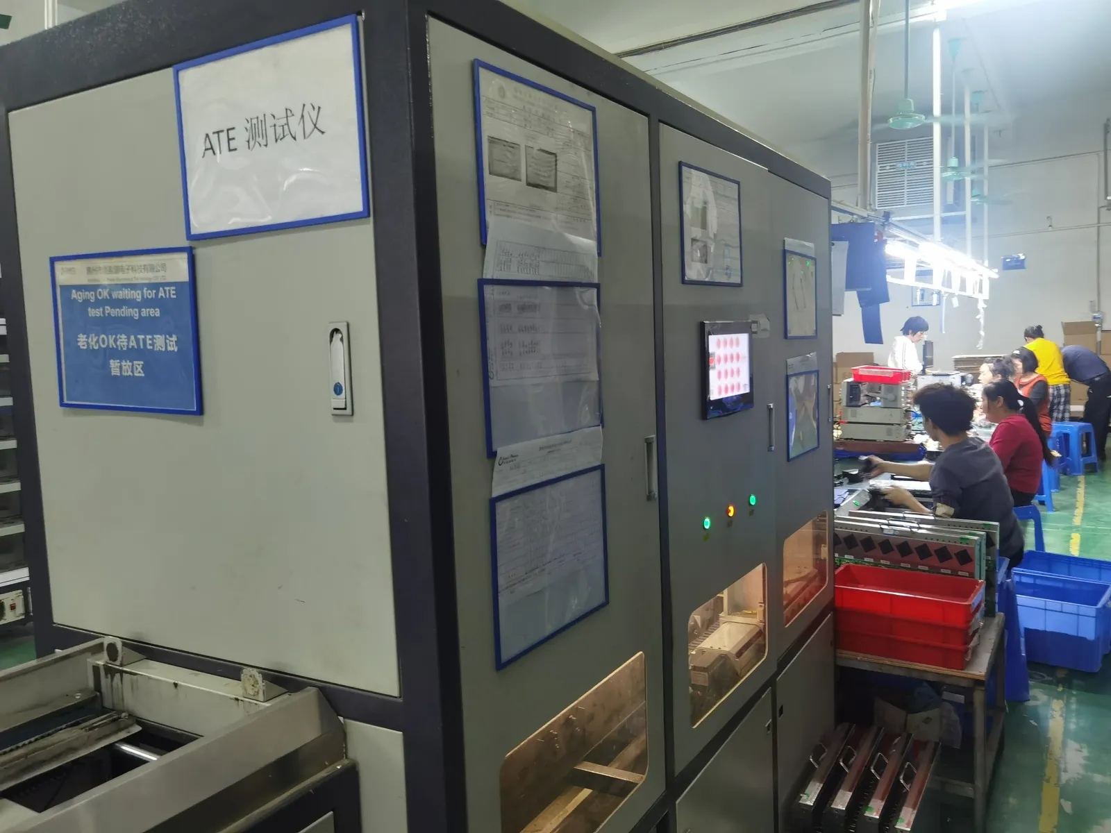
Why a 2xMOPP supply can still fail a 10 µA limit
This is the part of the topic that costs programmes the most time, and it deserves to be stated plainly.
An isolation rating answers the question “will the barrier survive?” It says nothing about the question “how much current flows across the barrier while it is intact?” Those are different questions, and the second one is governed by capacitance.
A 4000 V AC barrier can still pass tens of microamps of leakage current in normal operation, because any real barrier has capacitance across it — and at mains frequency, capacitance is a path. In practice, supplies described as medical grade with a genuine 2×MOPP construction can measure patient leakage in the range of several tens of microamps, which is comfortably acceptable for a BF application and comprehensively unacceptable for a CF one.
- The two requirements are independent. Withstand voltage is a survivability property; leakage is a continuous-flow property. Passing one tells you nothing about the other.
- A higher withstand rating does not reduce leakage. Making the barrier thicker and stronger does not necessarily make it a smaller capacitor — and the capacitor is what leaks.
- So the specification has to carry both lines. State the isolation level and the patient leakage limit your applied part requires. A supplier given only the first will quote a construction; a supplier given both will tell you honestly whether it is achievable.
- A supplier who knows the difference will ask you about the applied part. That question — before price — is the single best signal that you are talking to someone who has done this before.
For a BF device the distinction is academic, because a few tens of microamps is well inside the limit. For a CF device it is the whole project.
What actually drives leakage
If leakage is the hard constraint, it is worth knowing what sets it, because the levers are specific and they are all in the power supply.
- Transformer interwinding capacitance. The primary-to-secondary capacitance of the transformer is usually the dominant path. Medical-grade designs are specified for low interwinding capacitance — commonly quoted in the tens of picofarads — and the lower the better for patient-connected circuits.
- Y-capacitors across the barrier. These are placed for EMC compliance, and they sit directly across the isolation barrier. They are one of the main reasons a well-isolated supply still leaks: the capacitance that helps you pass EMC is the same capacitance that carries leakage current.
- Isolation components in the signal path. Optocouplers and digital isolators, feedback paths and any communication across the barrier each contribute their own coupling capacitance.
- Board layout. The physical separation of primary and secondary copper, and what runs alongside it, affects the effective coupling.
- Earth and enclosure paths. Not the barrier itself but the other leakage paths in parallel with it, which is why touch current and enclosure current are measured too.
The commercial consequence is that leakage is a system-level design outcome, not a component characteristic. Two supplies with the same transformer can have different leakage because of what else crosses the barrier.
Getting below the limit: what changes in the design
If your applied part requires the tightest limit, these are the levers that actually move the number — in rough order of how much they matter.
- Attack the capacitance, not the withstand. The transformer, the Y-capacitor arrangement and the signal-path isolators are where the microamps live. Optimising the dielectric withstand has no effect on them.
- Accept an EMC trade-off. The Y-capacitors exist for a reason. Reducing them for leakage reasons has to be compensated elsewhere in the filtering and shielding design, or the EMC result suffers.
- Consider a second isolation stage. A DC-DC stage on the secondary side is a common route to very low patient leakage, because the mains-derived barrier and the patient-facing barrier are then separate problems with separate budgets.
- Budget leakage across the whole device. The power supply is not the only path — cables, enclosures and the applied part itself contribute. A supply that consumes most of the allowance leaves the rest of the design nowhere to go.
- Measure with your cable and, if you can, in your enclosure. A leakage figure measured on a bare supply in a test fixture is a starting point, not the number your device will show.
The useful way to think about it: a patient-connected power supply is a capacitance management problem wearing an isolation rating on the outside.
Where the two barriers sit
Getting the architecture right on paper prevents most of the rework, because the barriers are in different places and are measured differently.
- Mains to secondary — the big barrier. This is where the 2×MOPP construction lives. It carries the full working voltage and needs the full creepage and clearance treatment.
- Secondary to earth and to touchable parts — the second barrier. Often overlooked. If the secondary floats but a signal line or an enclosure ties back to earth, that connection is itself a means of protection question.
- Applied part isolation. For BF and CF equipment the patient circuit must float with respect to earth within defined limits, which is a separate requirement from the mains barrier.
- Keep the barriers visible in the drawing. A marked-up diagram showing which barrier is which, and which components straddle it, is the single most useful document in the whole programme — and the one most often missing.
A supplier that cannot show you the barriers on a drawing has not designed a medical supply, however good the general-purpose product is.
Creepage, clearance and the board
Distances are confirmed on the printed circuit board and in the transformer, and that is where “we specified 8 mm” either survives or does not.
- Slots and cut-outs. An isolation slot increases creepage without increasing board area, and a routed slot is a common way to reach a distance that would otherwise need layout space you do not have.
- Edge distances and copper pours. Primary copper, secondary copper and any earth pour near the boundary each need checking; an innocent-looking ground pour can shorten a path.
- Component bodies count. Distances are measured over surfaces and through air around the components straddling the barrier, not only across bare board.
- Coating and potting change the answer. Conformal coating or encapsulation can be part of the insulation system, which is why the material specification belongs with the distance specification.
- Assembly tolerance. A distance that complies in the reference design must still comply in production, which is where written change control becomes a safety topic rather than an administrative one.
Because these distances are physical, a late change to the transformer, the board or the enclosure can invalidate work that took months. That is why the barrier drawing and the change-control process belong together from the start.
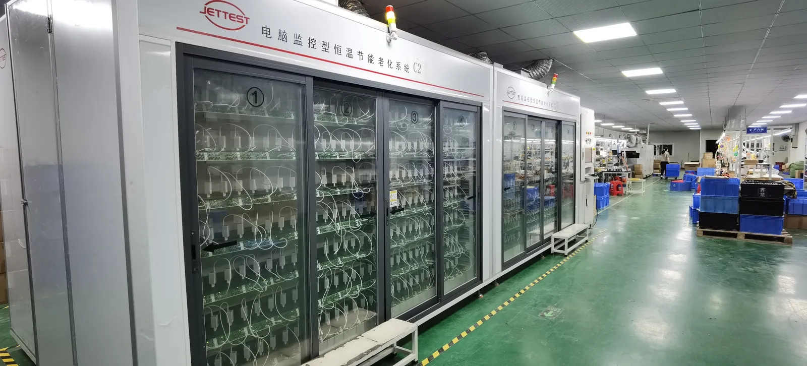
Evidence to demand
For a regulated device, the supplier’s documentation is an input to your own filing. These are the items worth asking for before price, not after.
- A barrier drawing. Which barrier is which, which components straddle it, and where the distances are measured.
- Measured leakage current under the conditions relevant to your applied part, with the test setup described.
- Dielectric withstand evidence for the barrier, at the level your classification requires.
- Interwinding capacitance and the Y-capacitor arrangement, because these are what set the leakage you will actually measure.
- Insulation material and system details, and whether coating or potting forms part of the insulation.
- EMC evidence against the medical collateral standard, since the filtering that achieves it interacts directly with leakage.
- Written change control, so that a component substitution cannot quietly alter a barrier you have already filed.
We are explicit about our position: we build custom and modified-standard supplies to IEC 60601-1 design requirements, including low-leakage and 2×MOPP isolation builds, and we do not claim a medical certification we do not hold. The certificates we do hold are CE, CB, FCC and ISO 9001. The device-level conformity is the device manufacturer’s filing, and our job is to make the supply’s part of that evidence solid. Our medical power supply selection guide covers the wider programme, and the sample evaluation checklist covers how to test the first article.
What this does to the build
Specifying a medical isolation level changes the physical product, and knowing which parts change makes the quotation conversation much shorter.
- The transformer. A low-interwinding-capacitance construction, typically with reinforced or double insulation and documented creepage, is a different and more expensive part than a standard commercial transformer.
- The board. Isolation slots, wider distances, material selection and coating add area, cost and process steps.
- The filter arrangement. Y-capacitor values are a compromise between EMC performance and leakage, and that compromise has to be designed rather than inherited.
- The feedback and signal path. Whatever crosses the barrier has to be chosen with its own coupling capacitance in mind, not selected for cost alone.
- Test time. More measurements, more documentation, more per-unit verification — which is real cost, and normally worth paying on a regulated product.
- Change control. Once a barrier is filed, substitutions stop being an engineering convenience and become a regulatory event.
The honest summary: a 2×MOPP, low-leakage build is a genuinely different product from a commercial supply of the same wattage, and it is priced and managed accordingly. Anyone quoting you the commercial price has not understood the requirement.
What to put in the RFQ
These lines turn an ambiguous medical enquiry into something a supplier can engineer and quote against.
- The applied part classification — Type B, BF or CF — because it drives everything else.
- The required isolation level in means of protection terms, and where each barrier sits.
- The patient leakage limit your classification requires, not just the isolation rating.
- Working voltage across the barrier, and the pollution degree and material group assumed.
- Which standard edition you are filing to, and in which market.
- EMC environment — professional healthcare or home healthcare — because the filtering requirement interacts with the leakage budget.
- Enclosure and mounting, since coating, potting and distances all depend on it.
- Change control and confidentiality terms, so the barrier you filed stays the barrier you ship.
All of it is easier to settle before tooling than after. The OEM agreement guide covers the contractual half of that.
MOOP vs MOPP specification table
| Item to specify | What to state | Why it matters |
|---|---|---|
| Applied part | Type B, BF or CF | Drives the isolation level and the leakage limit |
| Isolation level | 1× or 2× MOOP / MOPP, per barrier | A construction requirement, not a component choice |
| Dielectric withstand | Test level per barrier | Survivability, separate from leakage |
| Creepage and clearance | Values for your working voltage, material group and pollution degree | Not a universal constant such as 8 mm |
| Patient leakage limit | The figure your applied part requires, with the test setup | The requirement a 2×MOPP rating does not by itself satisfy |
| Interwinding capacitance | Measured value for the transformer | The dominant contributor to leakage |
| Y-capacitor arrangement | Values and position relative to the barrier | Where EMC and leakage requirements collide |
| Insulation system | Materials, and whether coating or potting forms part of it | Affects the distance calculation |
| Standard edition and market | The edition you file to, per region | Harmonisation timelines differ between markets |
| Change control | Written notice of any change touching a barrier | Protects your filing and your evidence |
Frequently asked questions
What is the difference between MOOP and MOPP?
MOOP protects the operator and MOPP protects the patient. MOPP is the stricter requirement because the patient may be unconscious, may have reduced skin resistance, or may be connected to the heart. The terms describe means of protection — barriers — not product categories.
Do I need 1×MOPP or 2×MOPP?
It follows from the applied part classification. Type B usually needs 1×MOPP, while Type BF and Type CF require 2×MOPP — and CF additionally has to meet the tightest leakage limit, which is the harder part of the problem.
Is 8 mm creepage a fixed requirement for 2×MOPP?
No — it is a widely used rule of thumb, not a constant. The governing values depend on working voltage, material group and pollution degree, and are read from the standard’s tables for your case. The 8 mm figure is useful for describing the construction you want, not for replacing the calculation.
Why can a 2×MOPP supply still fail a leakage limit?
Because isolation withstand and leakage current are different requirements. Withstand is about surviving an event; leakage is continuous flow across capacitance — mainly transformer interwinding capacitance and Y-capacitors. A genuine 4000 V AC barrier can still pass tens of microamps, which is fine for a BF device and far too much for a CF one.
What is the most important number for a patient-connected supply?
The patient leakage limit your applied part classification requires. For Type BF it is around 100 µA in normal condition; for Type CF it is around 10 µA. That second figure is what turns a medical power supply programme from routine into difficult.
How do you actually reduce patient leakage?
By attacking capacitance rather than the withstand rating. A low-interwinding-capacitance transformer, a careful Y-capacitor arrangement, and isolators in the signal path chosen for their own coupling capacitance. A second DC-DC isolation stage on the secondary side is a common route to very low patient leakage.
Does the applied part change the cable requirement?
Yes — a leakage figure measured on a bare supply in a fixture is only a starting point. The cable and the enclosure are part of the leakage path, so measure with your cable and, where possible, in the enclosure, and budget the allowance across the whole device rather than the supply alone.
What documentation should I request from the supplier?
A barrier drawing, measured leakage with the test setup described, dielectric withstand evidence, interwinding capacitance and Y-capacitor values, the insulation system, medical EMC evidence, and written change control. Those are the items that feed your own filing.
What MOQ and lead time apply for a 2×MOPP build?
From 200 pcs per model at Paiyi Power, with samples in about a week and first production 5–6 weeks after sample approval. We build to IEC 60601-1 design requirements including 2×MOPP and low-leakage constructions, and we do not claim a medical certification we do not hold — the certificates we hold are CE, CB, FCC and ISO 9001, and the device-level filing is the device manufacturer’s. See custom medical power supply for the wider programme.
Sources
- IEC — 60601-1 medical electrical equipment safety, including means of protection
- IEC — 60601-1-2 medical EMC collateral standard
- ISO — 14971 risk management for medical devices
- UL — 60601-1 certification for medical electrical equipment
- U.S. FDA — medical device premarket submissions and recognised consensus standards
Related on this blog: custom medical power supply selection guide, cobot power supply, how to test a power supply, why power adapters fail.