LED Power Supply OEM: Constant Voltage vs Constant Current Drivers, Dimming and IP Ratings for Lighting Brands
Published: September 2026
Reading time: 10 min
Audience: lighting brands, luminaire OEMs, LED strip and fixture manufacturers, and procurement teams sourcing LED drivers and power supplies
By Han — Paiyi Power, an OEM/ODM power supply manufacturer and LED power supply OEM partner building custom and modified-standard supplies from 5W to 240W, from 200 pcs per model.
Last updated: 15 September 2026.
Contents
Direct answer: what power supply does an LED product need?
An LED is a current-driven device, so the first decision is constant current or constant voltage: use a constant-voltage driver (usually 12V or 24V) when the LED strip or module carries its own current-setting resistors, and a constant-current driver when the LEDs are bare engines whose current you must set yourself — commonly 350, 500, 700 or 1050 mA within a stated voltage window. For any team choosing an LED power supply OEM partner, the three specifications that decide whether the product survives in the field are correct driver type and current, dimming compatibility, and thermal and life design — not the wattage printed on the box.
Get those three wrong and you get flicker at low dim, drivers that die at two years, and nuisance breaker trips. At Paiyi Power we build these from 200 pcs per model, with samples in about a week and first production in 5–6 weeks after approval.
Why LED power is its own discipline
A charger feeds a circuit that asks for a voltage. An LED asks for a current, and the voltage follows wherever the junction temperature takes it. Four consequences make LED power different from any other adapter category:
- The load is non-linear. A small change in forward voltage produces a large change in current, which is why driving LEDs from a fixed voltage and a resistor is a thermal compromise rather than a design.
- Forward voltage moves with heat. As the LED warms up, its forward voltage falls. A constant-current driver holds brightness steady; a badly matched constant-voltage design drifts brighter and hotter.
- Dimming is a compatibility problem, not a feature. The driver, the dimmer (wall or protocol) and the LED load must all agree. Mismatches show up as flicker, buzz or a useless bottom end.
- The driver is expected to outlive the fixture. LED lifetimes are quoted in tens of thousands of hours, so the driver’s electrolytic capacitors — not the LEDs — usually set the real service life.
That is why specifying an LED driver on wattage alone is the most expensive mistake in this category.
Constant voltage vs constant current
This is the single decision that shapes everything else, and it is decided by how your LED product is built — not by preference.
| Aspect | Constant voltage (CV) | Constant current (CC) |
|---|---|---|
| Typical output | 12V or 24V DC (48V for long runs) | Fixed current, e.g. 350/700/1050 mA, in a voltage window |
| Used for | LED strips and modules with on-board resistors; multiple parallel runs | COB, high-power single LEDs, luminaires with no on-board current limiting |
| Setting the light output | Watts per metre x metres; you buy enough supply capacity | You choose the current; brightness is whatever the LED bin gives at that current |
| Thermal behaviour | Current shifts with forward voltage; needs margin and good strip design | Current held constant regardless of temperature; more predictable |
| Voltage drop | A real constraint — long strips dim toward the end unless fed from both ends | Driver compensates; but the LED string must sit inside the driver’s voltage window |
| Typical efficiency | Good, and simpler; losses land in the strip’s resistors | Higher system efficiency; no resistor losses |
The practical rule: if your product has resistors built in, you want CV; if it does not, you want CC. Asking for the wrong one is the most common error we see in incoming specifications.
Matching the driver to the load
For a constant-current design, four numbers have to line up:
- Output current — set to the LED engine’s rated current, and the driver must hold it accurately across its input range.
- Voltage window — the driver’s output voltage range must cover the LED string’s forward-voltage spread, including the cold end. A 30–42V driver and a 36–40V string leave almost no headroom.
- Vf binning — LEDs are binned for forward voltage; the spread across bins is what eats your voltage headroom. Ask for the bin range, not just the typical value.
- Thermal end-stop — the driver needs over-temperature protection and, for enclosed fixtures, a lower maximum case temperature.
For a constant-voltage design the arithmetic is simpler — watts per metre times metres — but two habits matter: never load a CV supply to more than about 80% of its rating (strips are often understated), and feed long runs from both ends so the far end is not visibly dimmer.
Dimming: TRIAC, 0-10V, DALI and PWM
Dimming is where most LED projects quietly fail, because it is a system property rather than a driver property. The main options:
| Method | Where it fits | Watch out for |
|---|---|---|
| TRIAC / phase-cut (mains) | Retrofit residential; uses the existing wall dimmer | Low-load flicker and flashing; trailing-edge dimmers suit LED better than leading-edge |
| 0-10V / 1-10V (analog) | Commercial and industrial; simple, robust, widely specified | Needs an extra control pair; dimming curve differs between brands |
| DALI | Addressable commercial lighting, building control | Higher driver cost; commissioning expertise required |
| PWM (internal) | Consumer products, RGB, colour tuning | Low-frequency PWM causes visible flicker and camera banding |
| Wireless / smart | Connected and tunable-white products | Standby power and always-on connectivity add to the energy budget |
Two rules cut most dimming support calls: specify the dimmer and the driver together, and test the bottom 10% of the dimming range, not the middle. Problems live at the bottom.
Flicker, and why it is a specification
Flicker is the failure mode nobody puts in a datasheet until it matters. It becomes obvious when a camera films a lit room, when a dimmer is near its bottom end, or when someone is sensitive to it.
- Source: low-frequency PWM dimming is the usual cause; the LED is switched on and off fast enough to look steady to the eye but not to a rolling shutter or to a sensitive viewer.
- Fix: use high-frequency PWM or constant-current reduction (analog) dimming for camera-facing and premium applications.
- Specify it: ask for a flicker figure and a dimming curve. IEEE 1789 is the usual reference for acceptable flicker levels; add “flicker-free at 25% dim and below” to the specification in plain words.
If a product is designed for video, broadcast or retail photography, flicker belongs in the requirements list, not in the post-mortem.
Efficiency, power factor and harmonics
LED drivers are judged on more than efficiency, and in commercial lighting the extra numbers are mandatory rather than optional:
- Power factor (PF). For loads above roughly 25W, many markets expect PF of 0.9 or better; poor PF means more current for the same watts and can breach installation limits.
- Harmonics. Lighting equipment is subject to the IEC 61000-3-2 Class C limits; this is the standard that separates a real lighting driver from a repurposed adapter.
- System efficiency and heat. Driver losses become heat inside the fixture, and heat is what shortens the capacitor life that sets the driver’s real lifetime.
Higher efficiency is therefore worth more than the electricity it saves — it buys life.
Inrush and breaker coordination
This is the specification that causes the most embarrassing commissioning failures, and it is invisible on a datasheet that only lists input power.
LED drivers draw a very high inrush current for a few milliseconds as their input capacitors charge. Ten of them on one breaker can trip it at switch-on even though the running load is trivial.
- Ask for the inrush figure (peak current and duration) rather than “soft start”.
- Specify inrush limiting (usually an NTC) where many drivers share a circuit.
- Coordinate with the breaker type — a B-curve MCB tolerates far less inrush than a C-curve.
Fixing inrush after a building is wired is far more expensive than specifying it before.
Thermal design and driver life
The driver is usually the shortest-lived component in an LED fixture, and its life is set by temperature:
- Capacitor rating. A 105 °C electrolytic lasts several times longer than an 85 °C part at the same internal temperature. This is the highest-value specification change available in this category.
- Case temperature and derating. Drivers inside sealed luminaires run far hotter than on a bench; require a maximum case temperature and an ambient derating curve.
- Potting where it counts. For outdoor and vibration-exposed products, full encapsulation removes internal air and the condensation path that outdoor drivers otherwise suffer from.
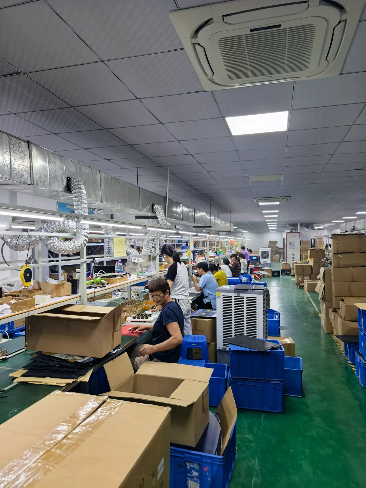
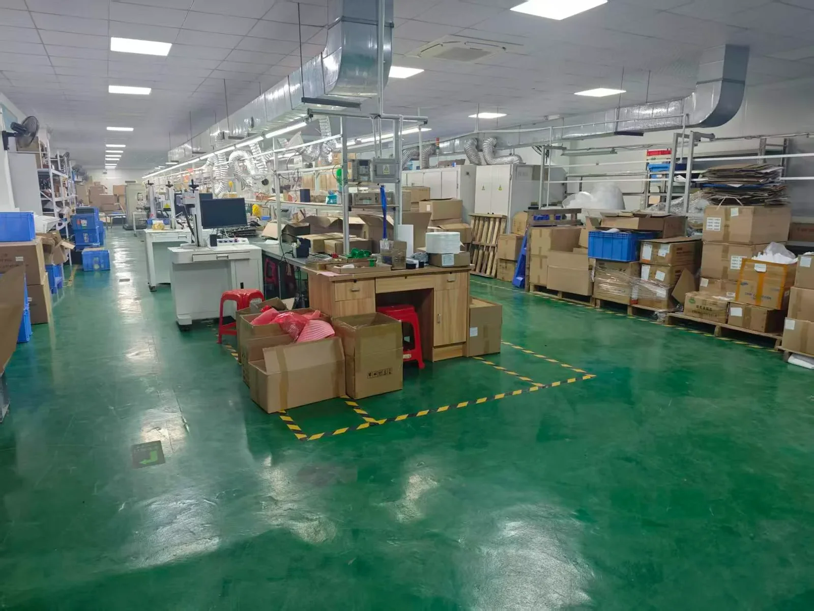
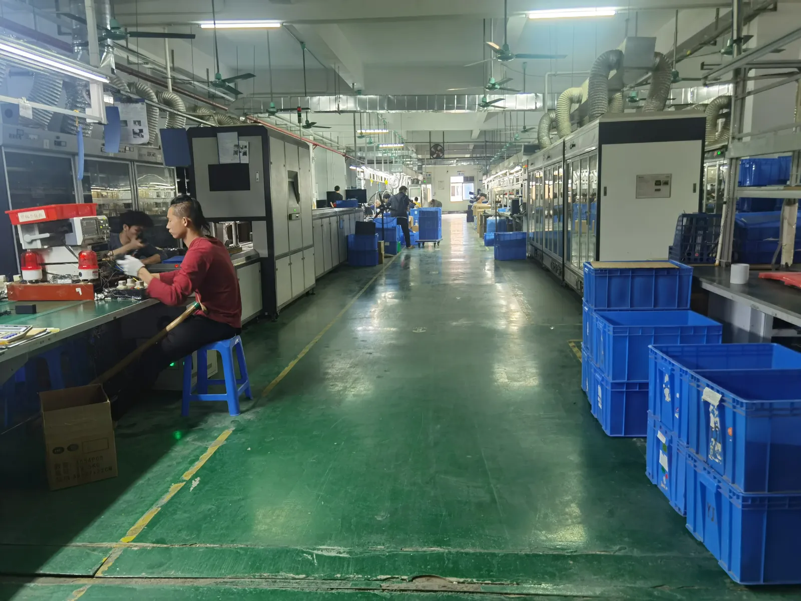
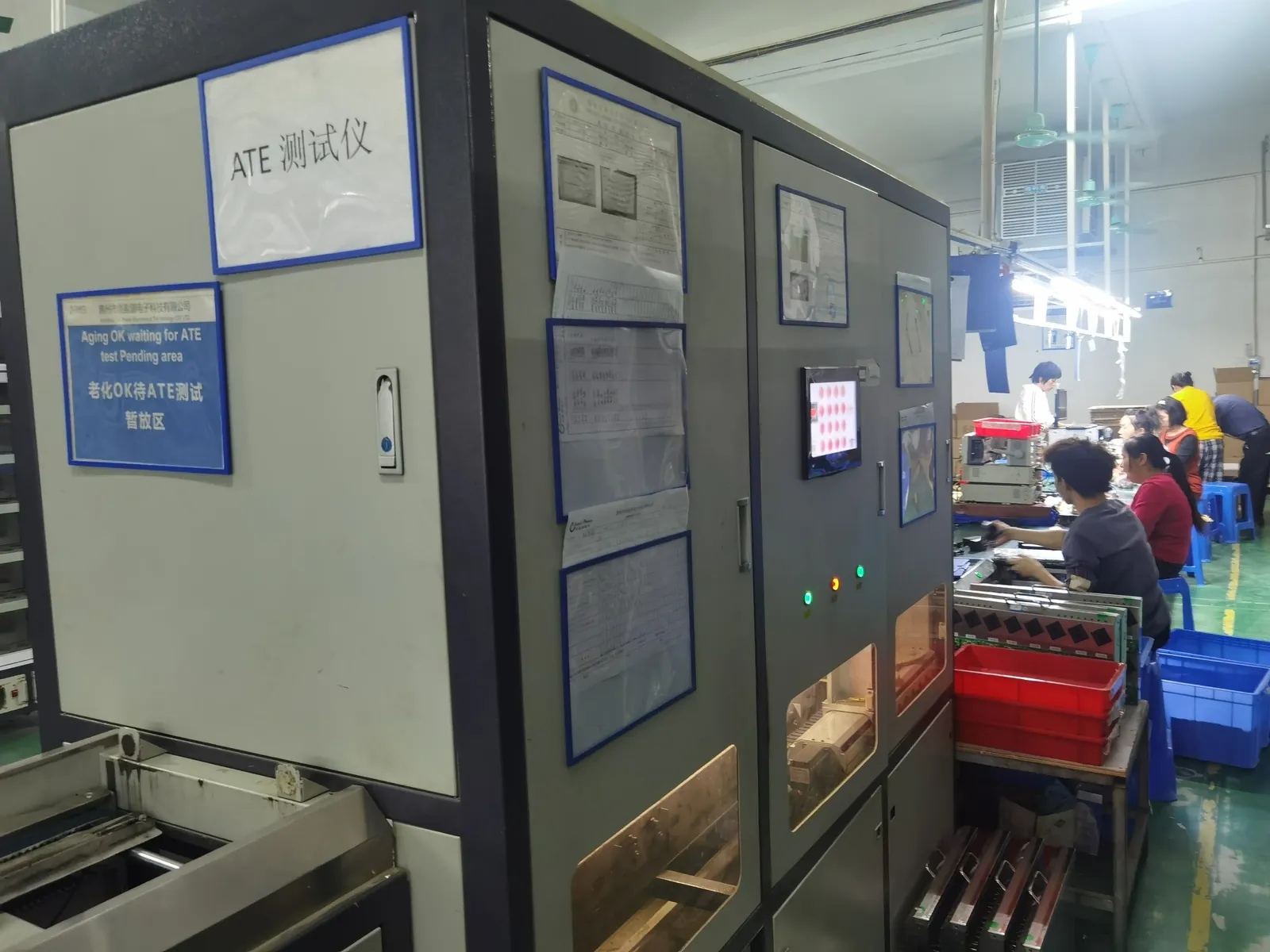
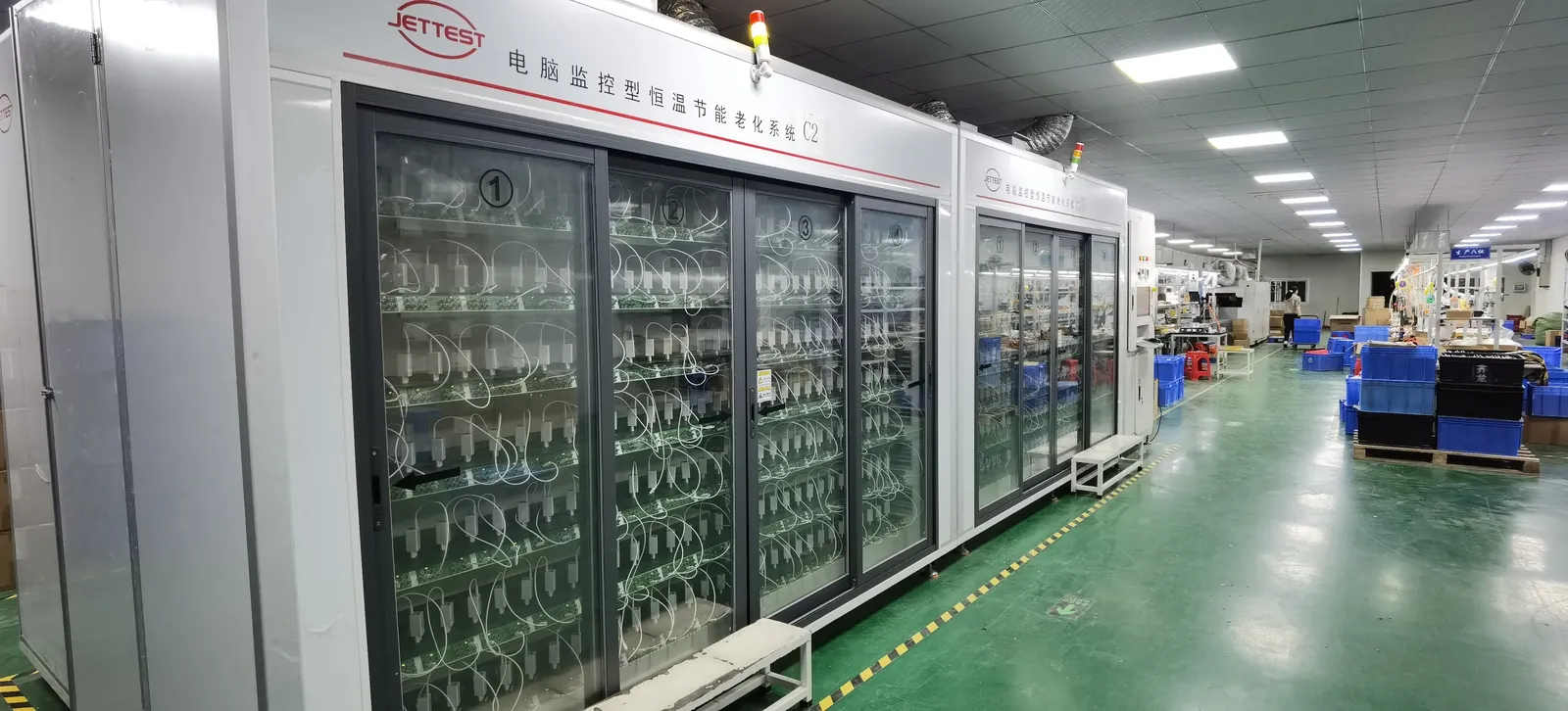
Every unit we ship goes through 100% ATE functional testing and a burn-in period before packing, and boards are built by qualified partner SMT houses with incoming inspection at our factory — assembly, test and aging are in-house.
Indoor, outdoor and IP ratings
Where the driver lives decides its enclosure, and the requirements are stricter than most buyers expect:
- Indoor (IP20) — inside a ceiling void or a luminaire body; the constraint is heat, not water.
- Outdoor (IP65–IP67) — sealed and preferably potted; the practical enemies are condensation and UV, not rainfall, which is why a fully sealed driver that still breathes through its cable gland eventually fails.
- Wet and damp locations — some regions require an explicit wet-location rating for the luminaire and the driver; this is a listing requirement, not a preference.
- Surge — outdoor, street and area lighting often specify IEC 61000-4-5 surge levels far above indoor values, because long pole-mounted runs collect transients.
It is the same discipline we describe for outdoor signage in digital signage power supplies.
Certifications: what actually applies
LED drivers sit under a different safety standard from ordinary adapters, and one very common misconception is worth correcting:
- Safety: the IEC/EN 61347 series (61347-1 and 61347-2-13) is the standard for lamp controlgear including LED drivers. In North America, UL 8750 covers LED equipment and UL 1310 covers Class 2 supplies. Some constructions are also assessed under the IEC 62368-1 framework.
- EMC and harmonics: IEC 61000-3-2 Class C for lighting, plus the usual emissions standards for the destination market.
- DoE Level VI does not apply to LED drivers. Level VI is an external power supply regulation; lighting has its own efficiency and quality programmes — notably the DesignLights Consortium (DLC) qualified products list and California Title 24 for commercial projects. If a supplier answers “Level VI” to a lighting efficiency question, they are answering a different question.
- SELV and Class II: confirm which insulation class your installation expects, because it changes the construction and the cost.
We certify per model and per market rather than claiming one certificate covers everything; certification by country explains which schemes transfer and which need local registration.
LED power supply specification table
| Parameter | Typical for LED lighting | Note |
|---|---|---|
| Driver type | CV 12V/24V for strips; CC 350–1050 mA for engines | Set by whether the LED has on-board resistors |
| Dimming | TRIAC, 0-10V, DALI or PWM — matched to the load | Test the bottom 10% of the range |
| Flicker | High-frequency PWM or analog; flicker-free below 25% dim | Required for camera-facing applications |
| Power factor / harmonics | PF 0.9+ above ~25W; IEC 61000-3-2 Class C | Lighting-specific, not adapter-grade |
| Inrush | Figure stated; NTC limiting where many share a breaker | Causes nuisance MCB trips at switch-on |
| Thermal | 105 °C capacitors, max case temperature, ambient derating | Driver life = capacitor life |
| Enclosure | IP20 indoor; IP65–IP67 potted outdoor | Condensation and UV, not rain |
| Safety standard | IEC/EN 61347 series; UL 8750 / UL 1310 in North America | Not the same as a generic adapter |
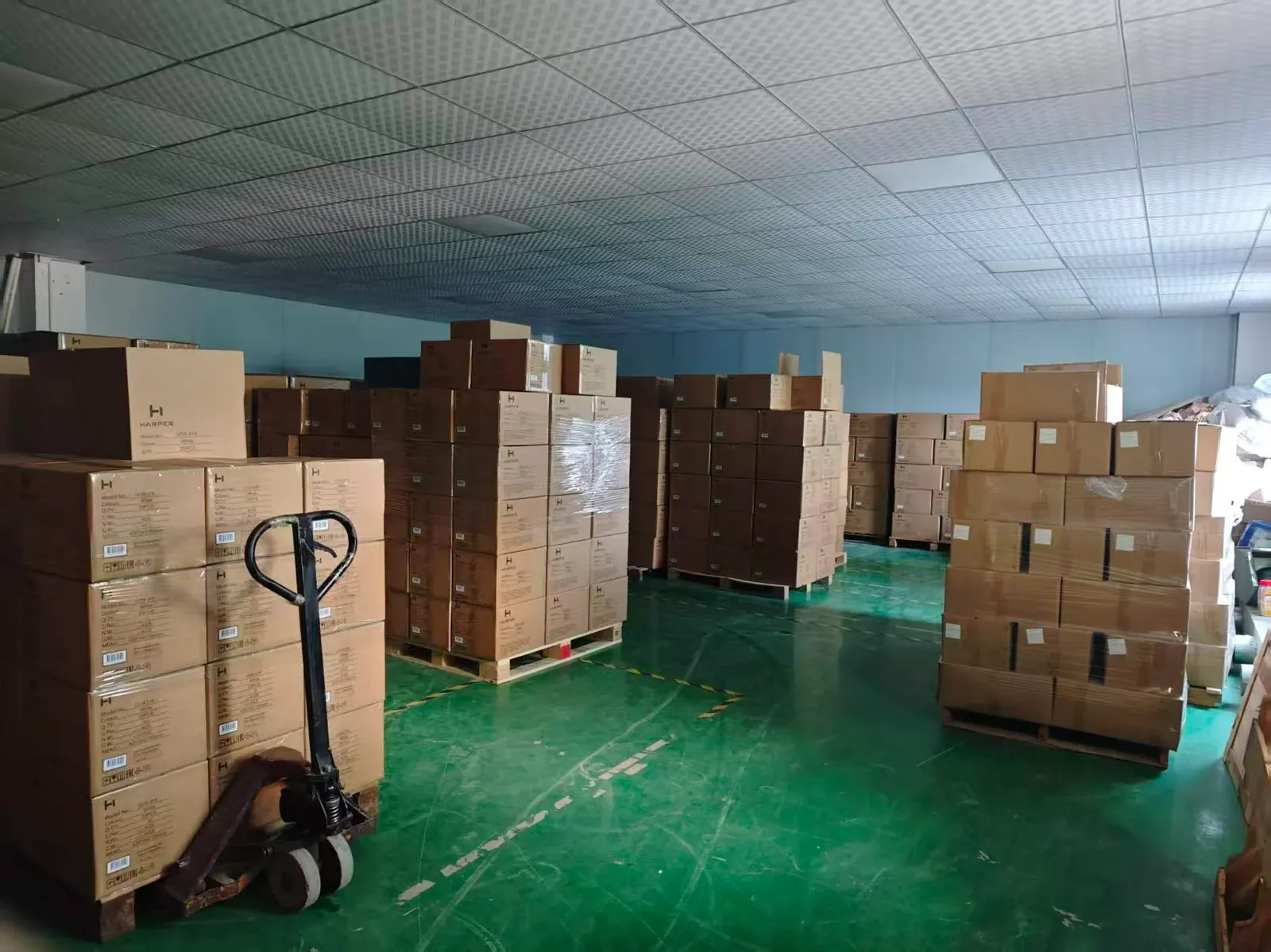
| Reliability | 100% ATE + burn-in; written change control | Fleets outlive product cycles |
Frequently asked questions
Do I need a constant voltage or a constant current driver?
It depends on whether your LED product contains its own current-setting resistors. Strips and modules with on-board resistors want constant voltage (12V/24V); bare COB and high-power engines without resistors want constant current, specified in milliamps.
Should I choose 12V or 24V?
24V for almost anything with a long run or meaningful power; 12V for short, low-power runs and legacy compatibility. At 24V the current is halved, so voltage drop along the strip is roughly a quarter of the 12V case and the far end stays evenly lit.
Which dimming method should I specify?
Analog 0-10V or DALI for commercial projects, TRIAC for residential retrofit, PWM for colour and consumer products. Whichever you pick, specify the dimmer and driver together and test the bottom 10% of the range — that is where incompatibilities appear.
How do I avoid flicker?
Use high-frequency PWM or constant-current (analog) dimming, and ask for a flicker figure and dimming curve. Standard mains dimming at very low loads is the classic source, and any application involving a camera should treat flicker as a hard requirement.
Which safety standard applies to LED drivers?
The IEC/EN 61347 series (61347-1 and 61347-2-13) for lamp controlgear, with UL 8750 and UL 1310 in North America. It is a different standard from the 62368-1 world of generic adapters, and a supplier who does not know the difference is a risk.
Do LED drivers need DoE Level VI?
No — Level VI is an external power supply regulation, not a lighting one. Lighting has its own programmes, notably the DesignLights Consortium qualified products list and California Title 24 for commercial work. If a supplier promises “Level VI” for an LED driver, you are discussing the wrong standard.
How do I size a driver for an LED strip?
Watts per metre x metres, then keep the load at or under about 80% of the supply rating. Strips are often understated, and leaving 20% headroom also keeps the driver cooler, which directly extends its life.
Why do breakers trip when the lights switch on?
Inrush current. Drivers charge their input capacitors in the first milliseconds and can draw many times their running current. Ask for the inrush figure, specify NTC limiting where several drivers share a circuit, and allow for breaker curve when coordinating.
What MOQ and lead time apply for custom LED power supplies?
From 200 pcs per model at Paiyi Power, with samples in about a week and first production 5–6 weeks after sample approval. An LED power supply OEM should also fix the specification before tooling: use our sample evaluation checklist and the OEM agreement guide for change control.
Sources
- IEC — 61347 lamp controlgear, 61000-3-2 harmonics, 61000-4-5 surge
- UL — 8750 LED equipment and 1310 Class 2 power supplies
- FCC — Part 15 rules (Class A / Class B digital devices)
- U.S. DOE — External Power Supply efficiency (Level VI, does not cover LED drivers)
- DesignLights Consortium — qualified products list for commercial lighting
Related on this blog: digital signage power supply OEM, CCTV camera power supply OEM, external power supply efficiency standards, why power adapters fail.